Kit Assembly
In this tutorial you will assemble your Mote. It should take around 15 minutes.
Gather Parts
First, check that you have the required parts. Missing something? Check out the sourcing guide.
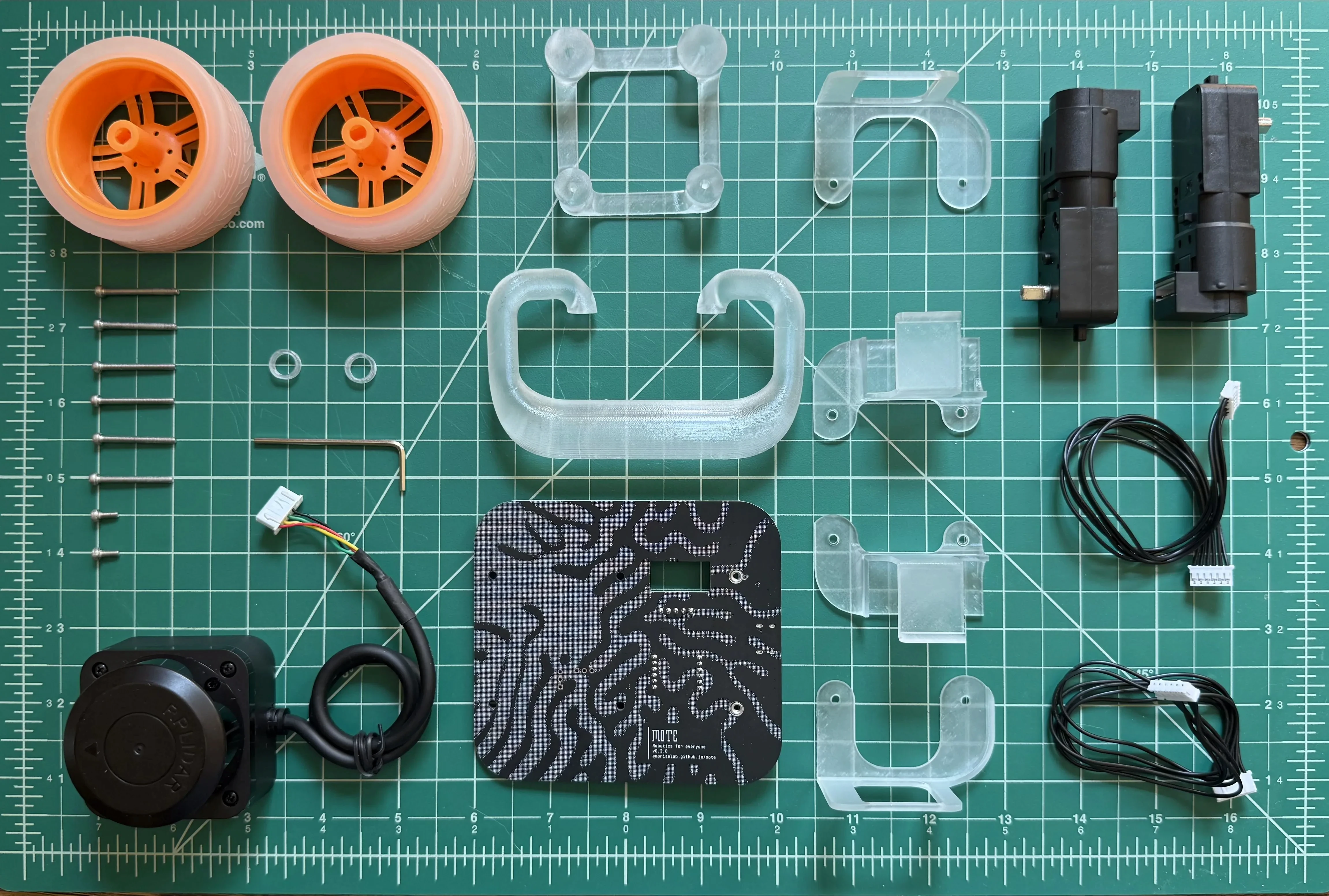
| Item | Quantity | Picture |
|---|---|---|
| Circuit Board | 1 | 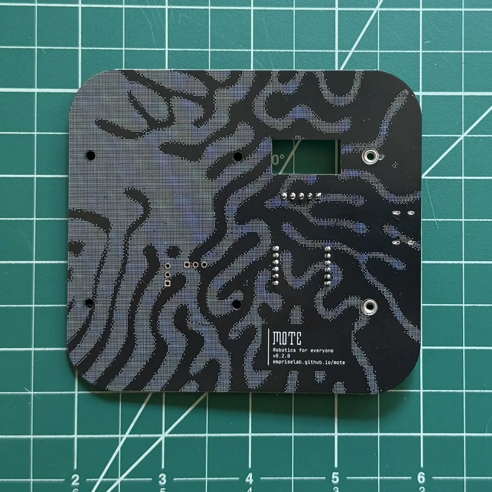 |
| Left Motor Mount | 1 | 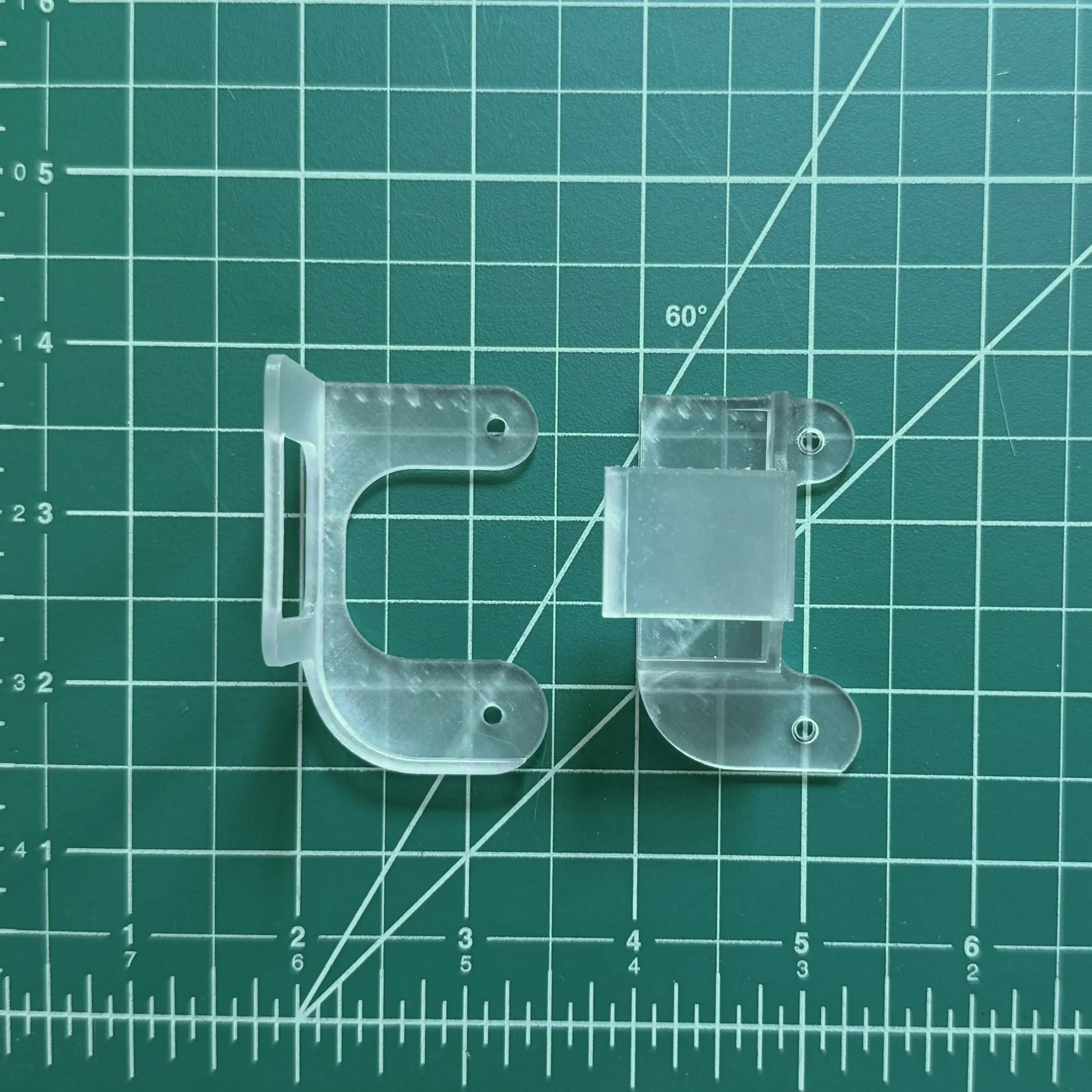 |
| Right Motor Mount | 1 | 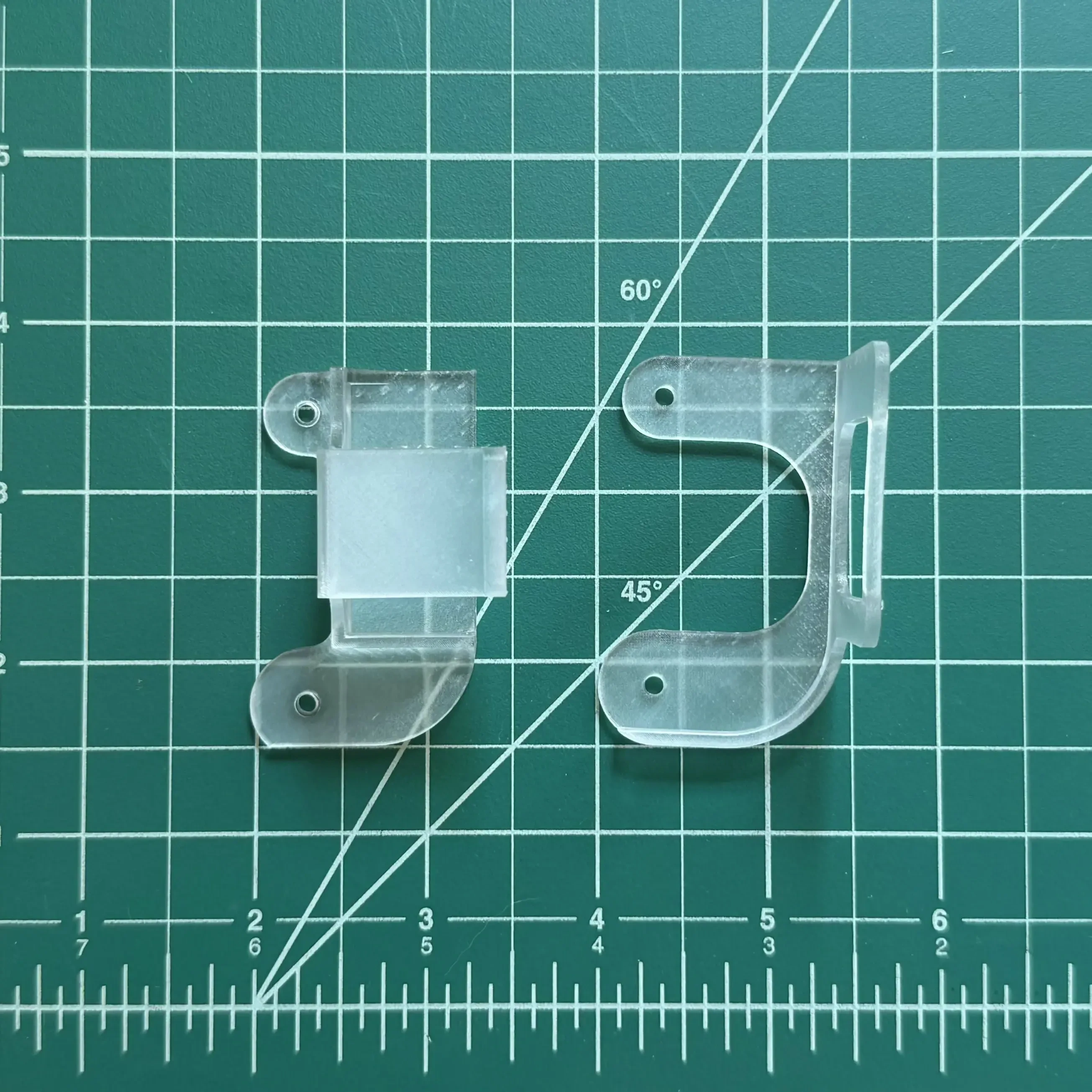 |
| Tail Runner | 1 | 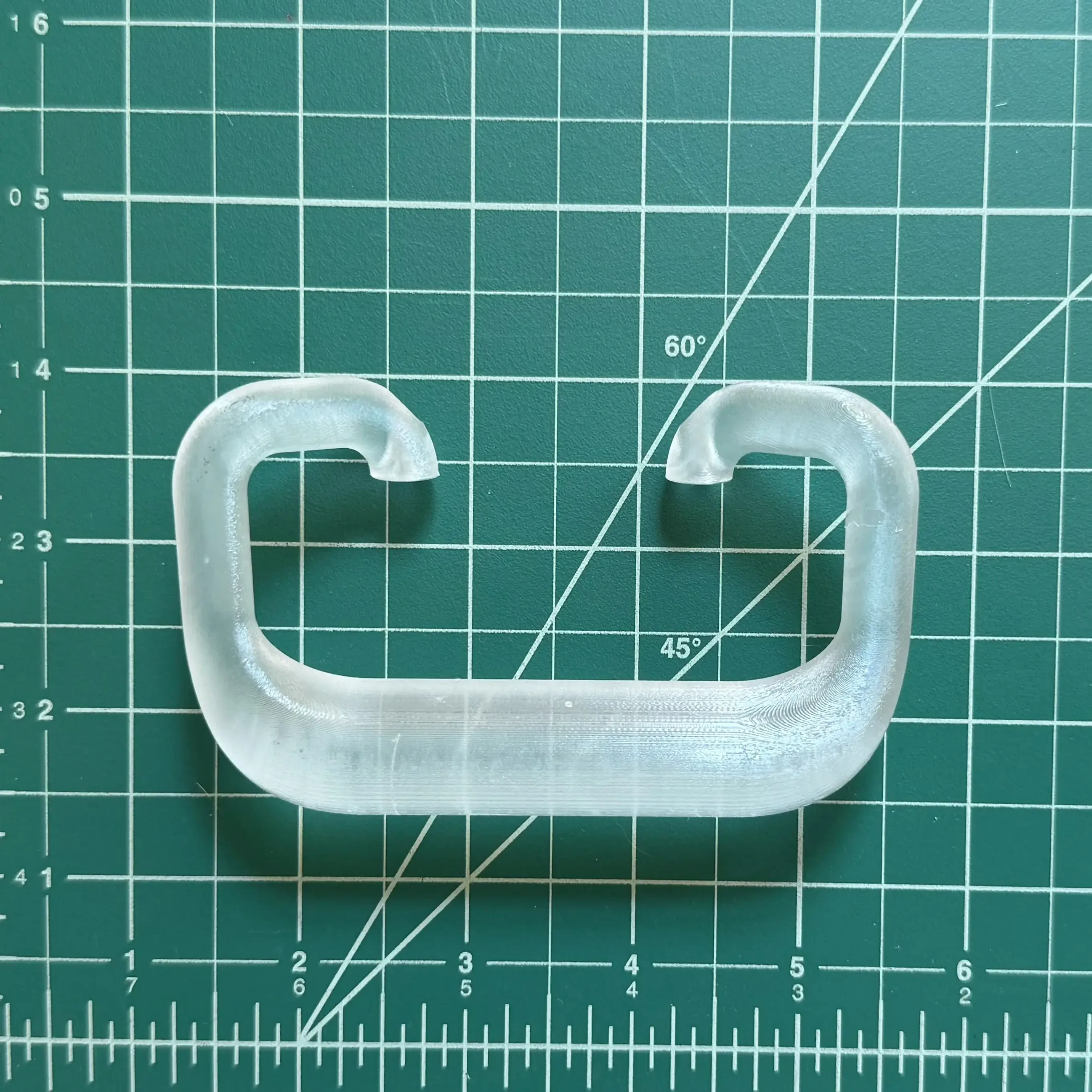 |
| LiDAR Mount | 1 | 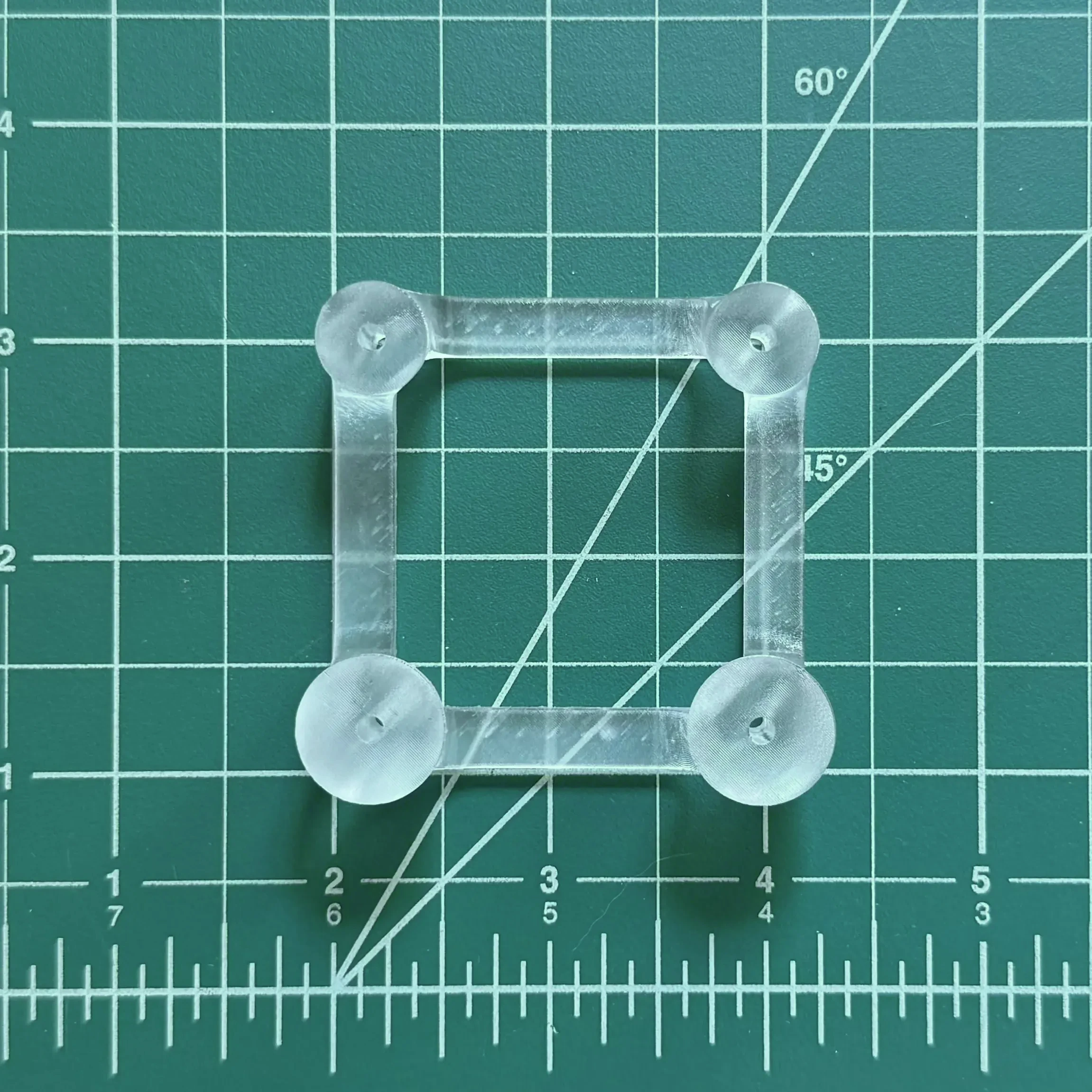 |
| Wheel Spacers | 2 | 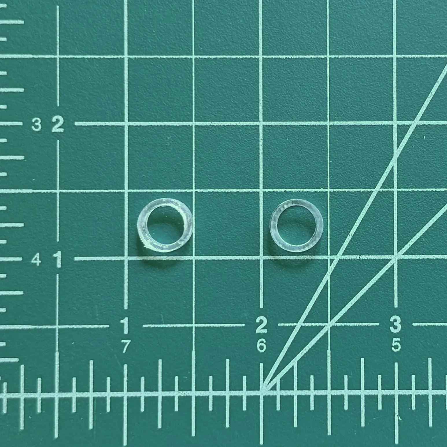 |
| LiDAR | 1 | 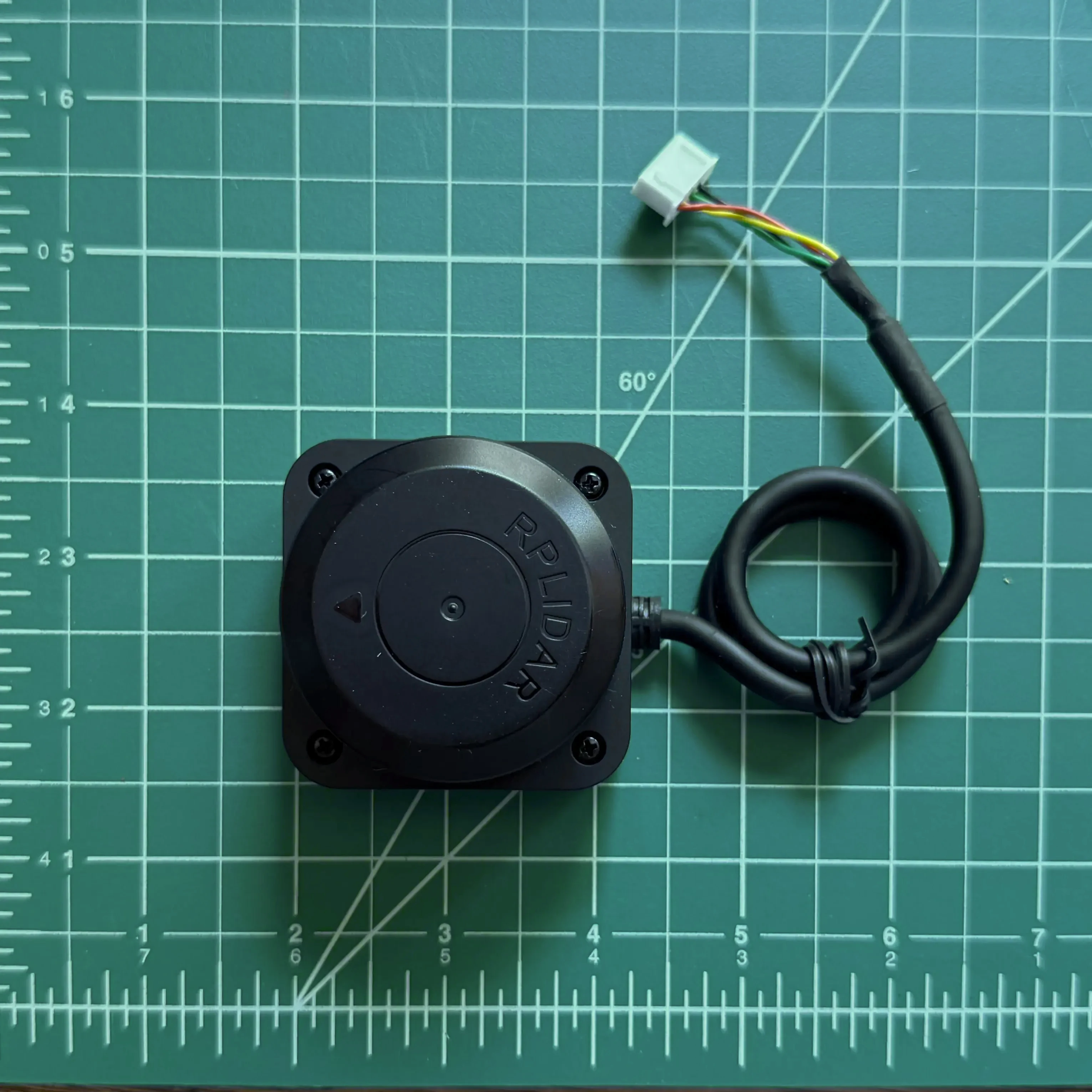 |
| Orange Wheel | 2 | 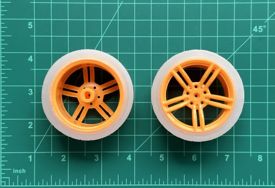 |
| Motor with Encoder | 2 | 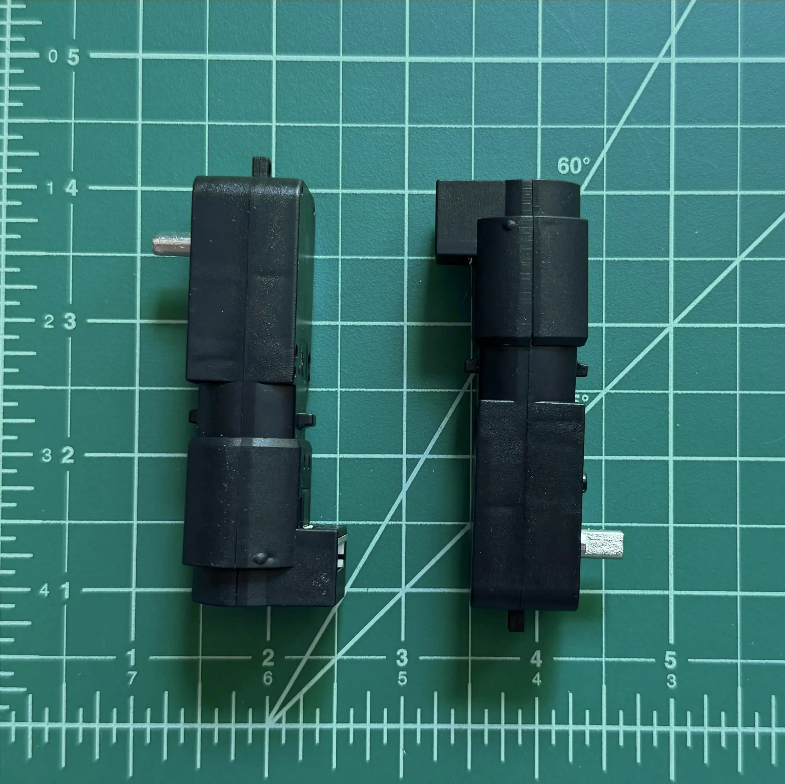 |
| 25mm M2.5 Hex Head Machine Screws | 6 | 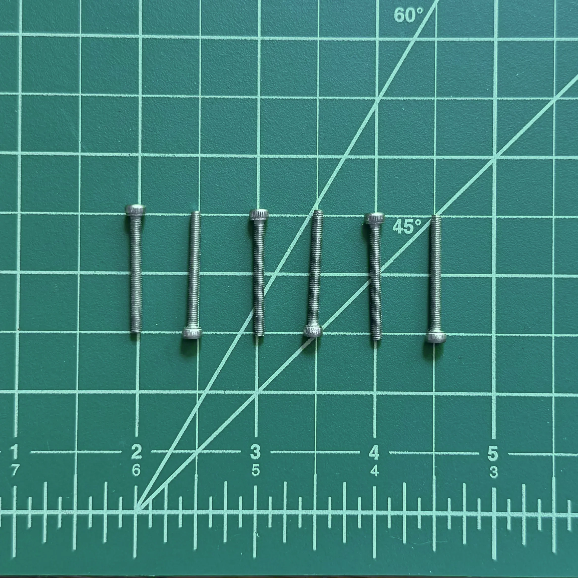 |
| 6mm M2.5 Hex Head Machine Screws | 2 | 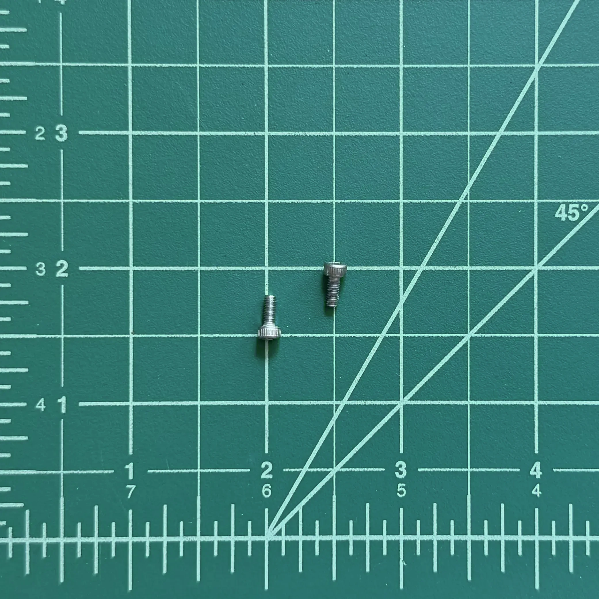 |
| 2mm Hex Key | 1 | 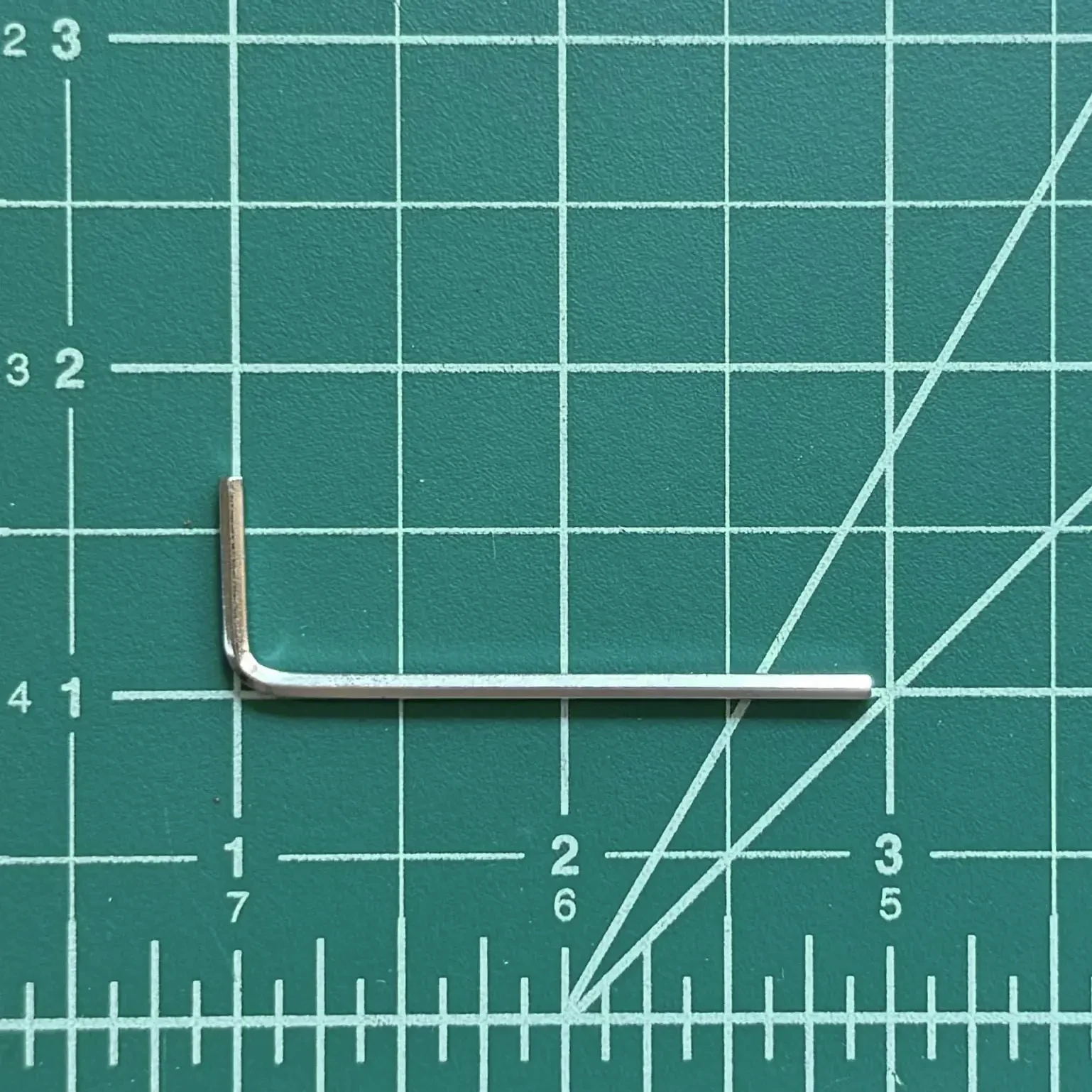 |
| USB-C to C Cable | 1 | 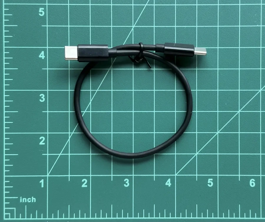 |
| 5000 mAh USB Portable Battery | 1 | 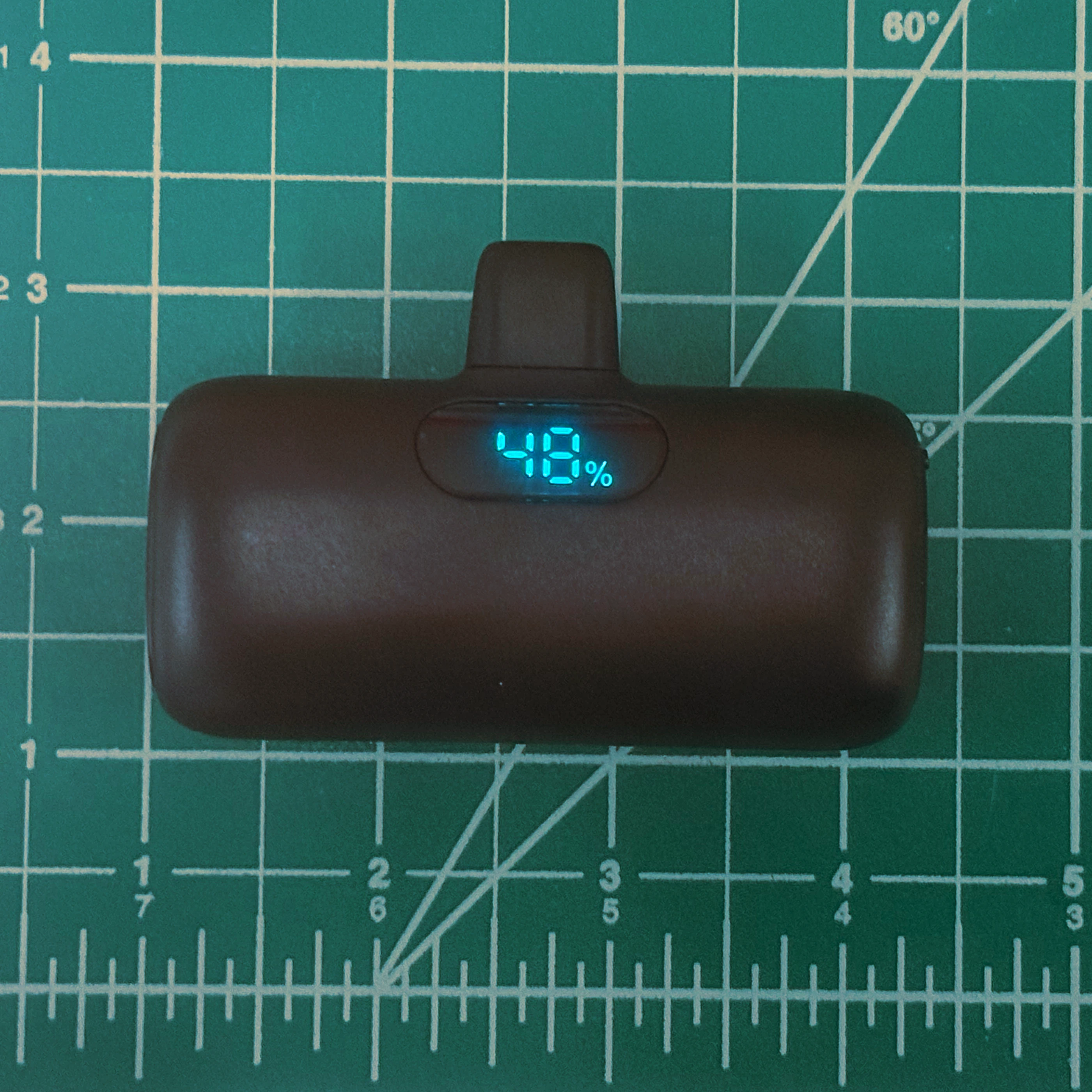 |
Motor Subassembly
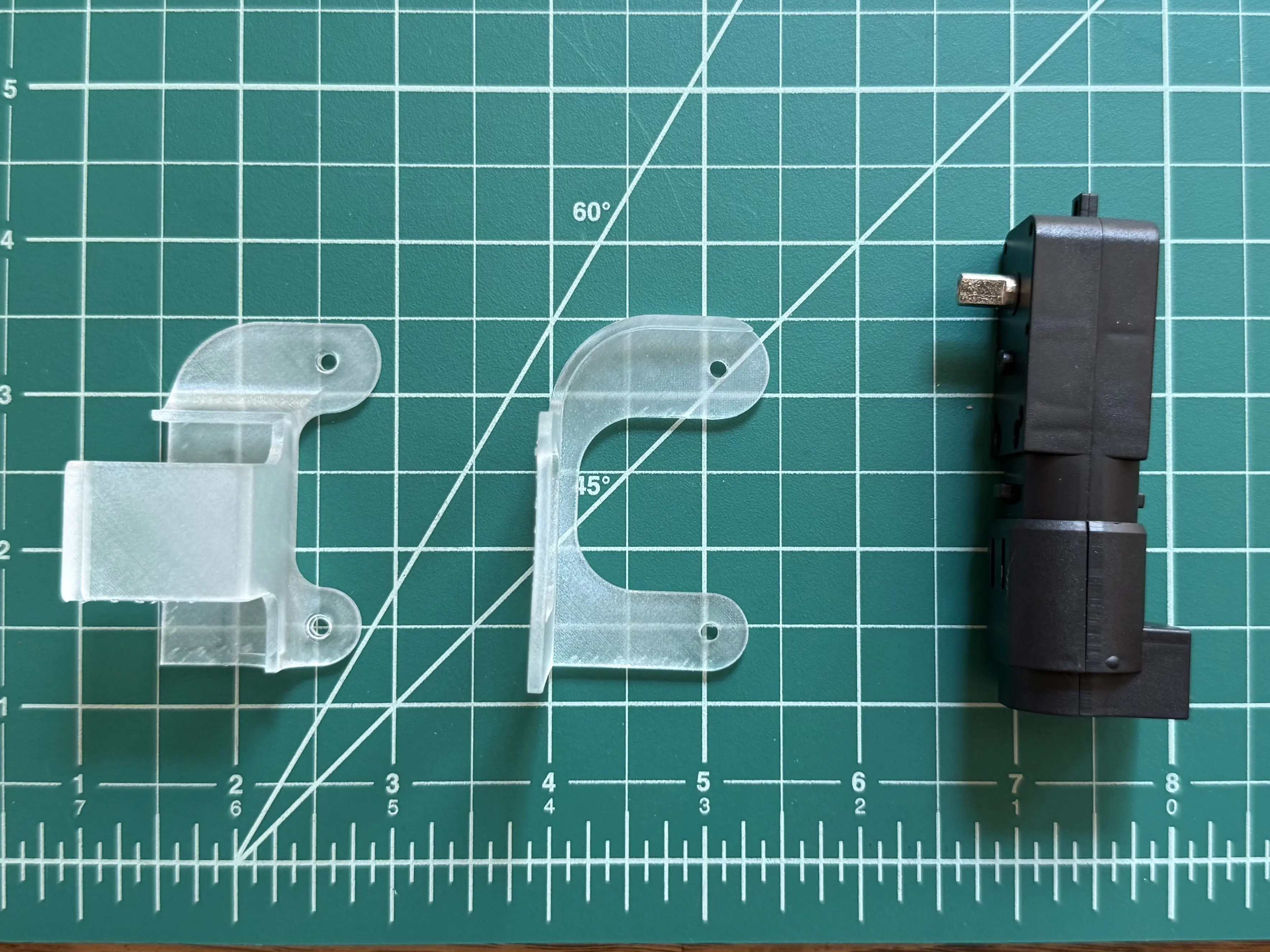
Place the motor into the bottom half of the motor mount. Ensure that the motor is seated in the pocket of the mount.
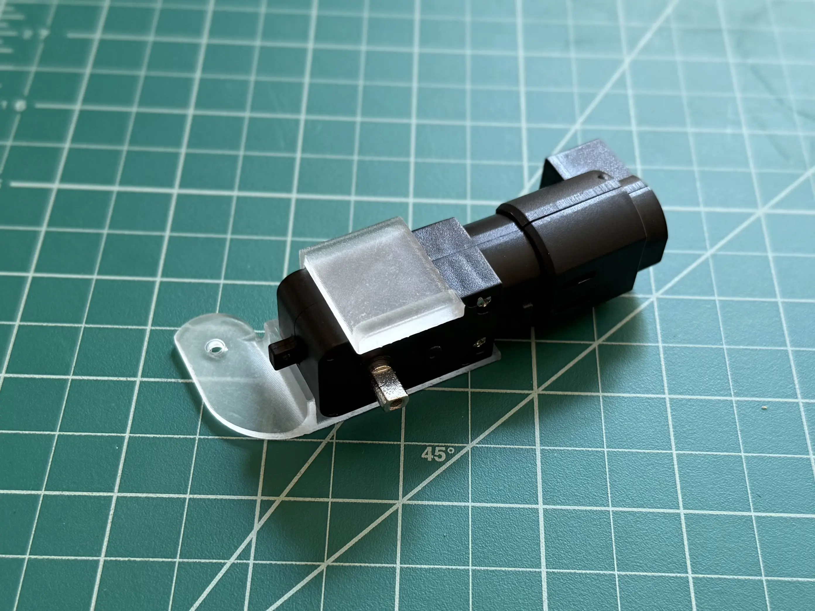
Connect the top side of the motor mount to the bottom side, securing the motor.

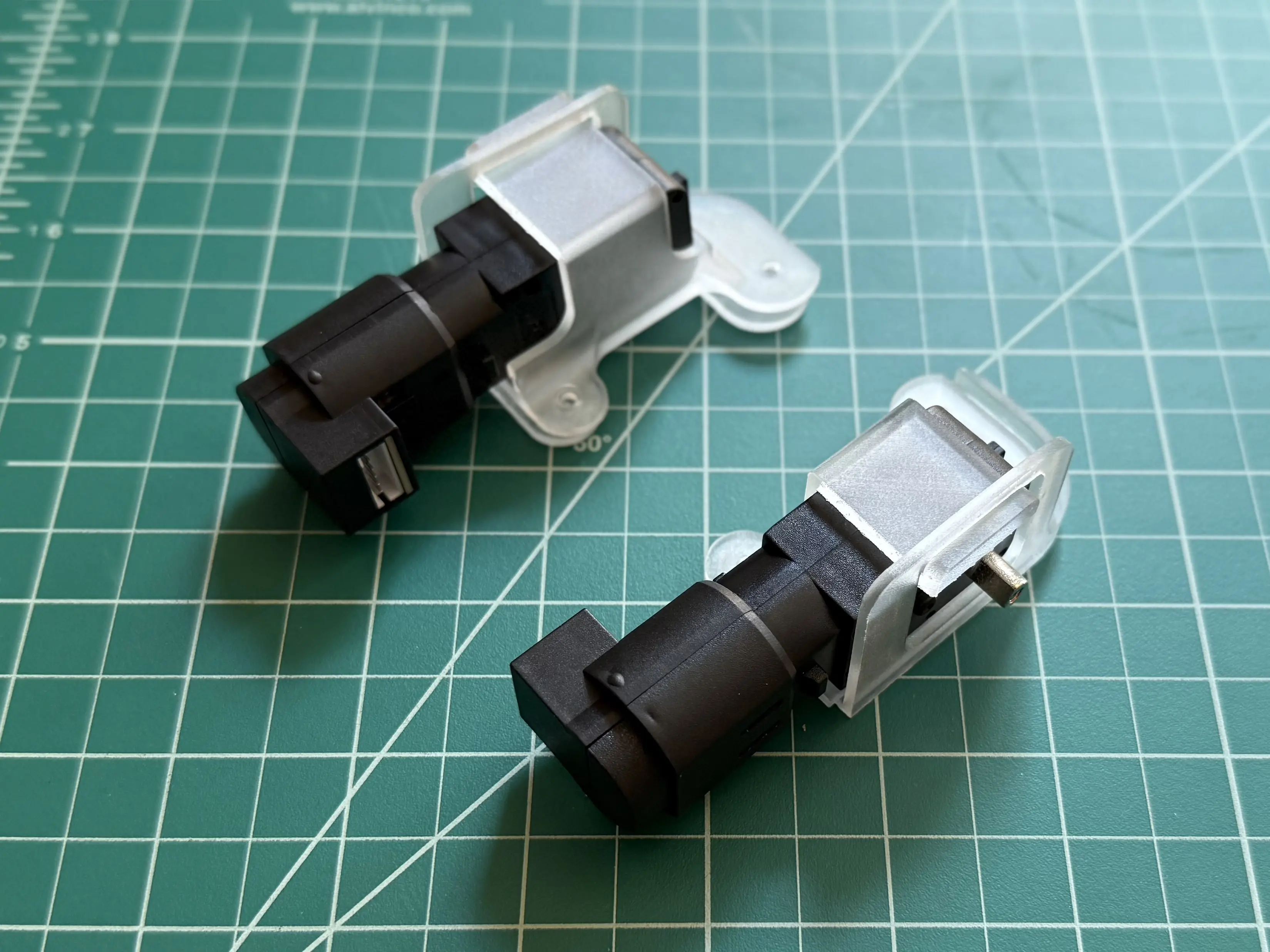
Repeat for the left side motor mount.
Body Assembly
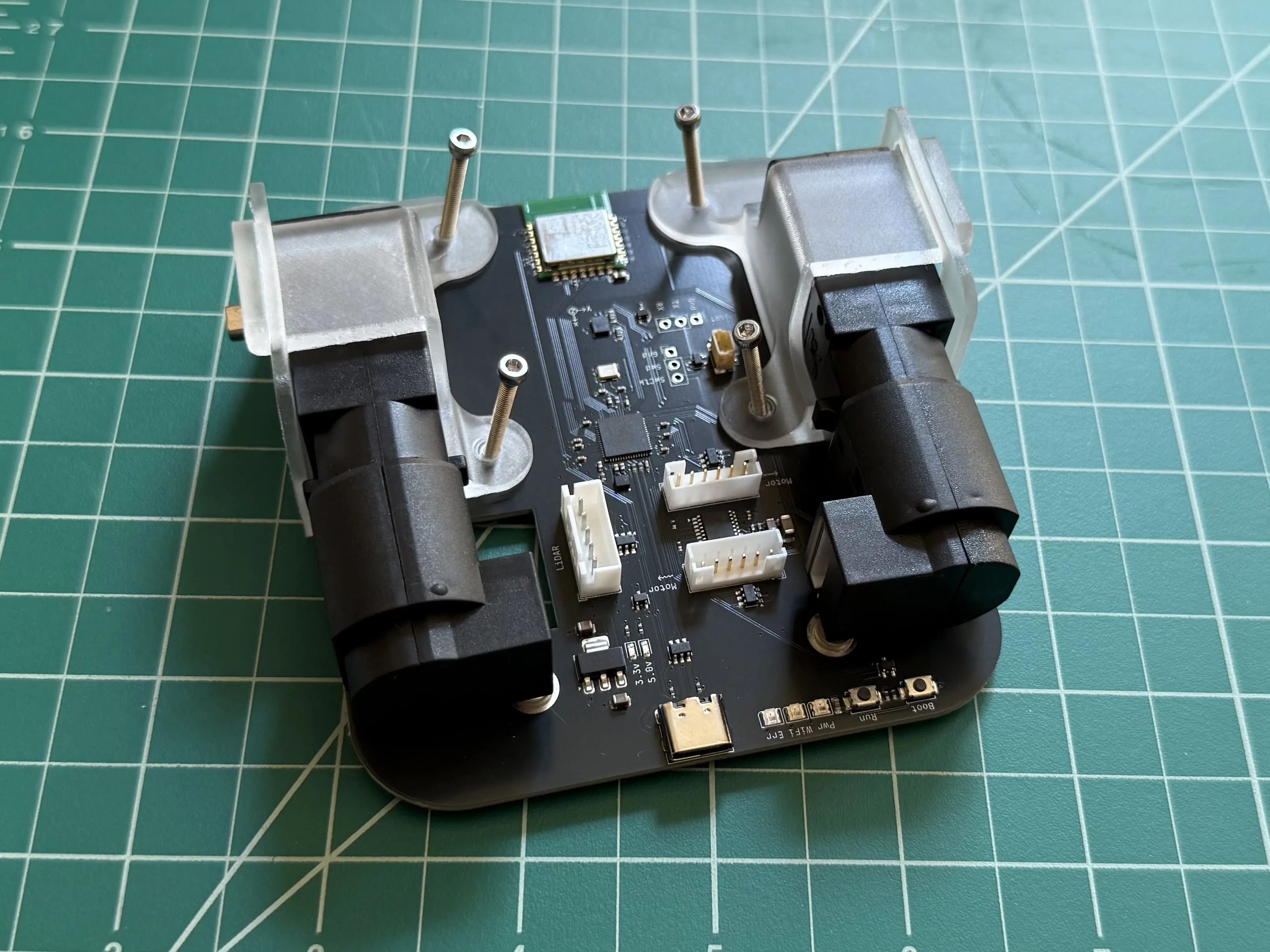
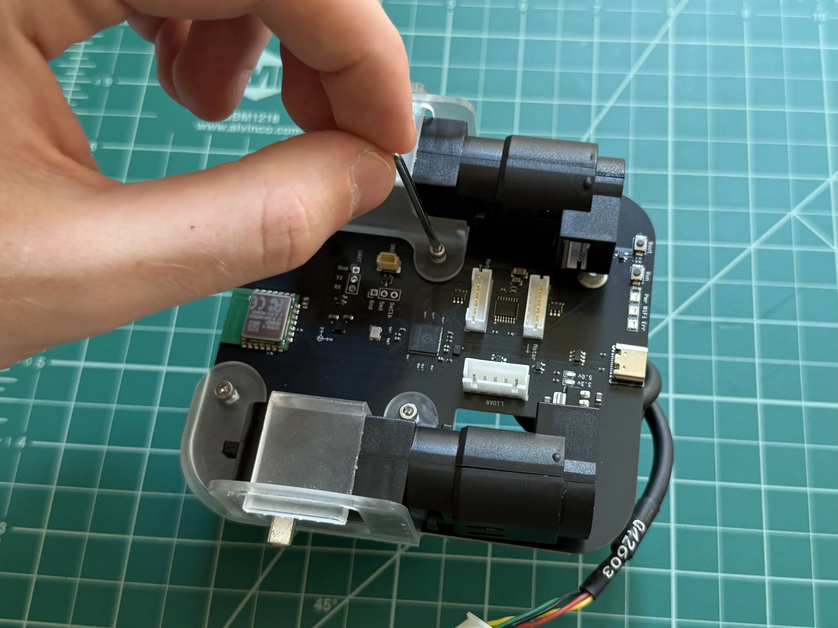
Slide the circuit board between the two halves of the motor mounts, aligning the holes in the mounts with those in the circuit board.
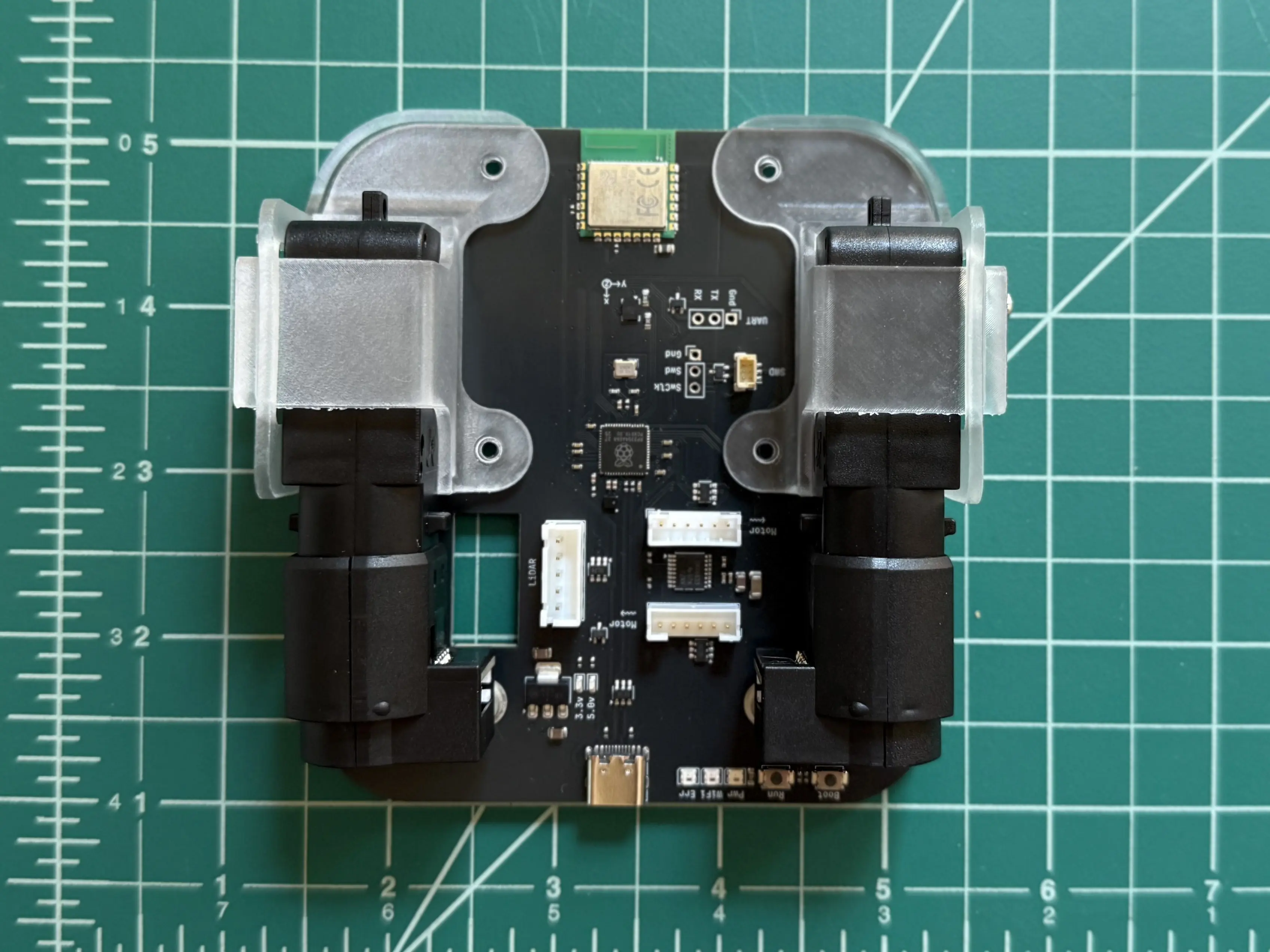
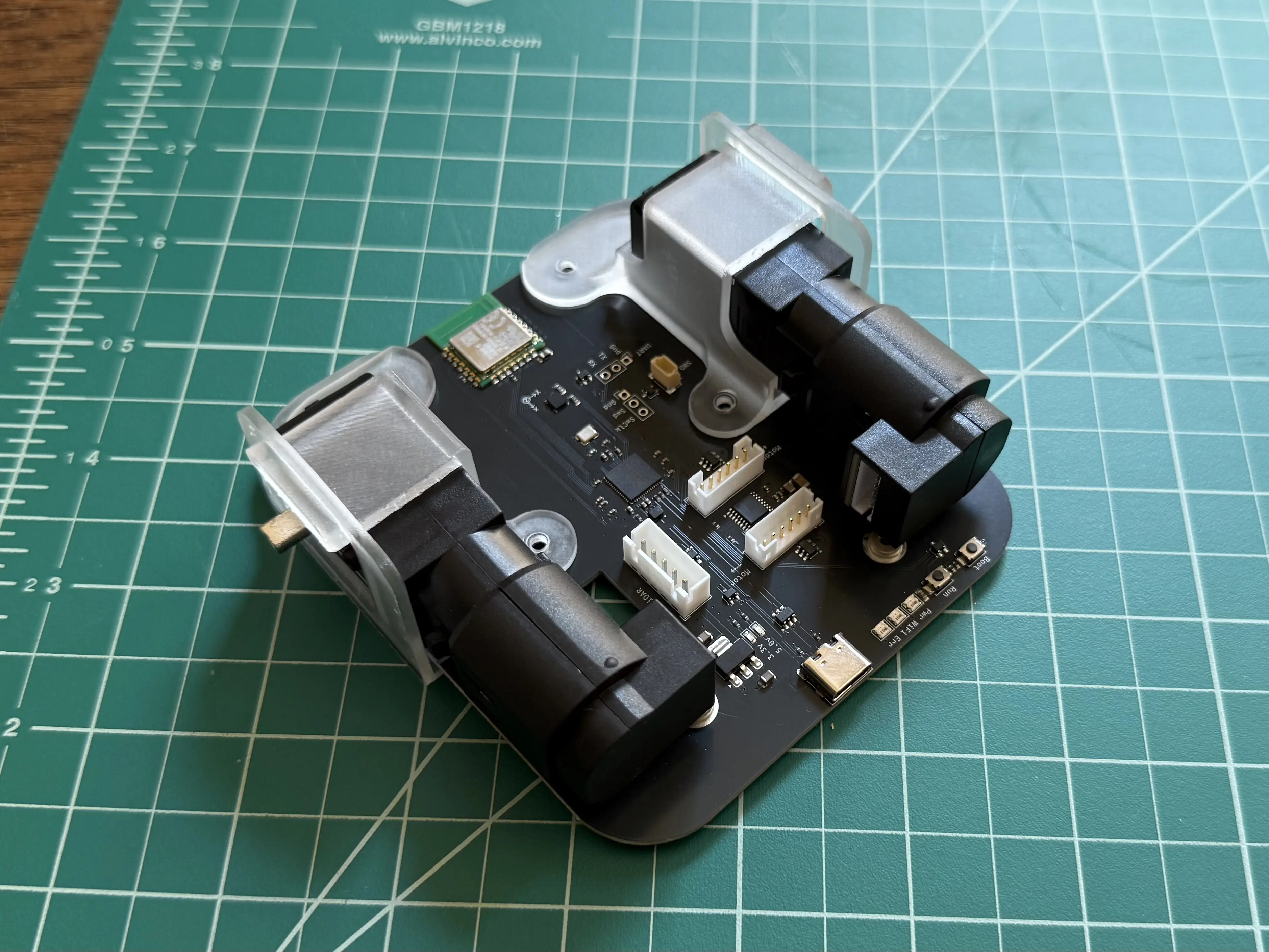
Insert the 25mm screws through the holes in the motor mounts and circuit board.
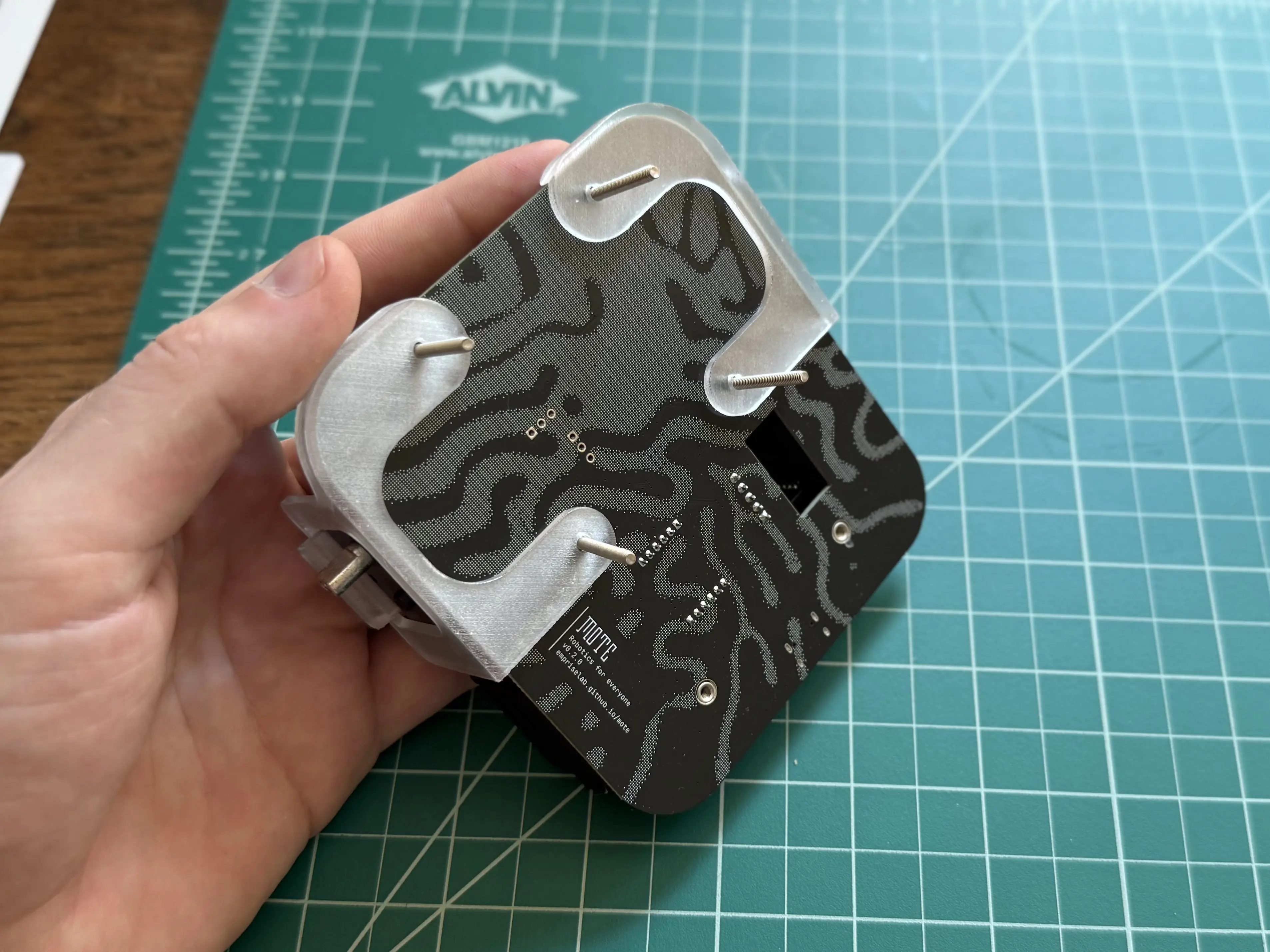
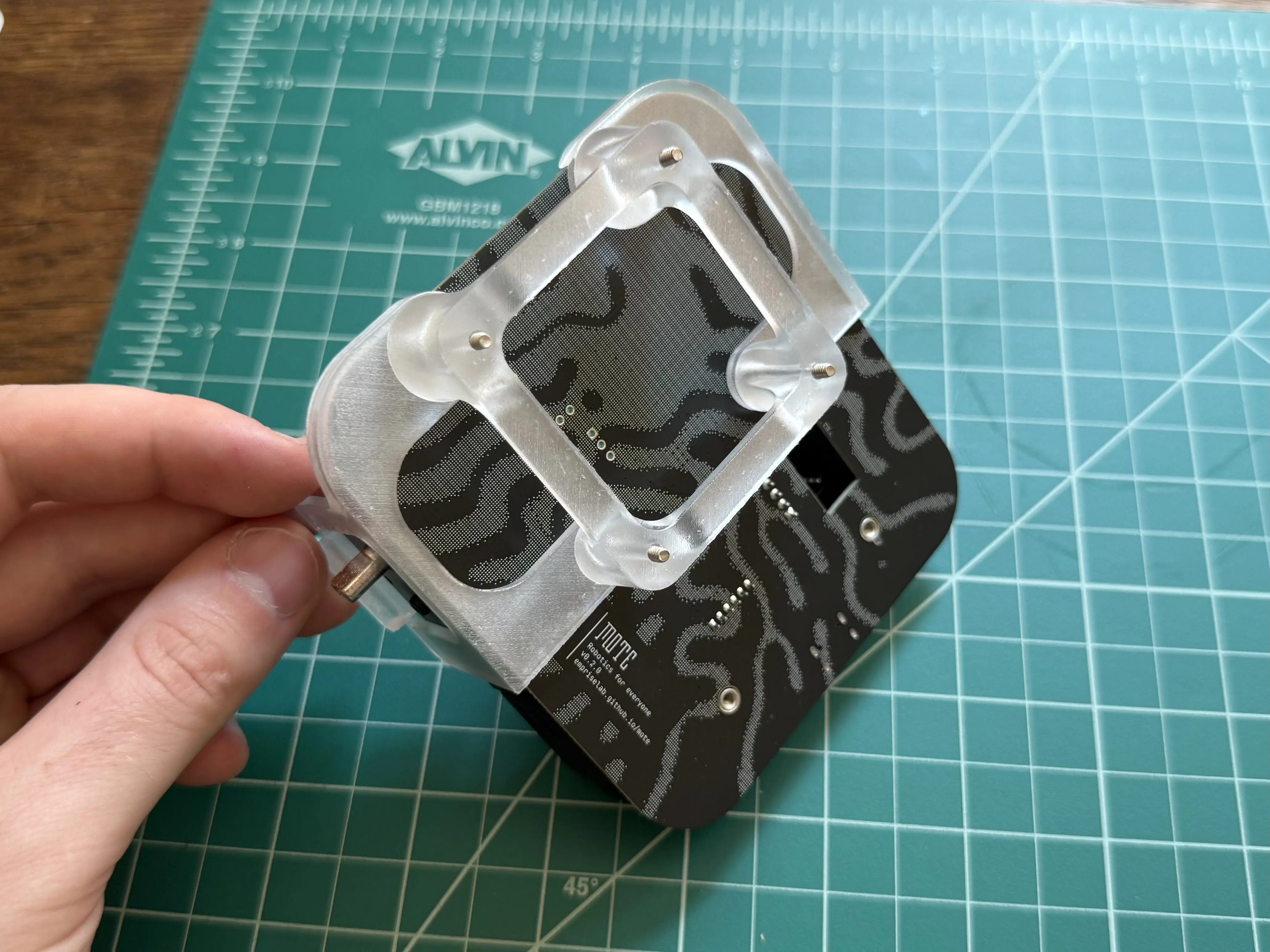
Place the LiDAR stand onto the 25mm screws.
Tip
The legs of the LiDAR stand are not all the same size. Match the radius of the legs with the radius of the motor mounts the legs are placed on.
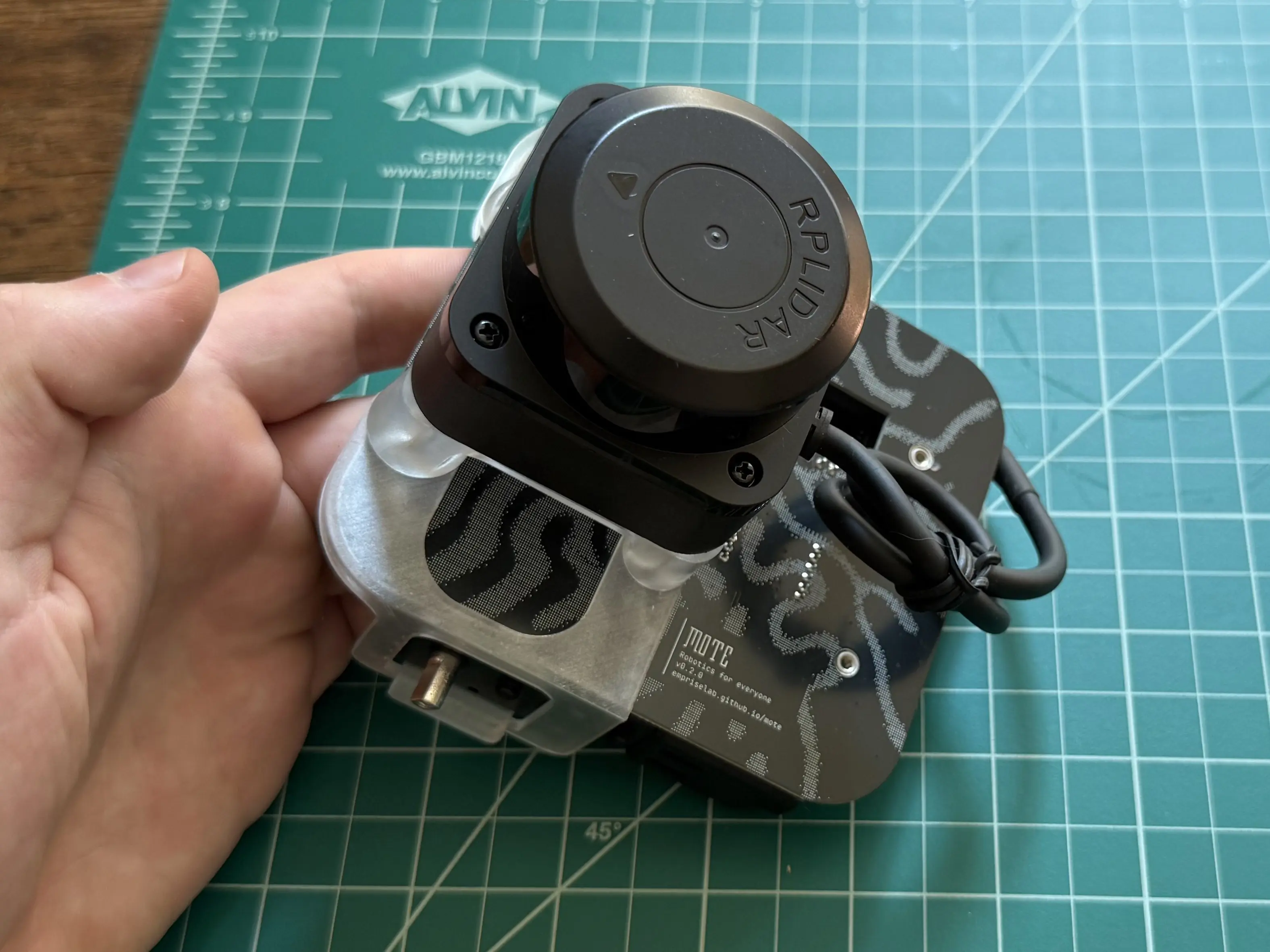
Place the LiDAR on top of the LiDAR stand, then thread the 25mm screws into the LiDAR’s base.
Cables
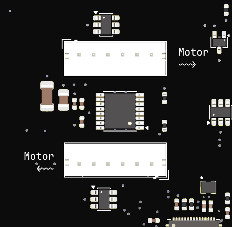
Connect both motors to the circuit board.
Important
It matters which motor is connected to which socket. Look for the “Motor” arrows on the silkscreen. The arrow points to the motor that should be connected to the respective socket.
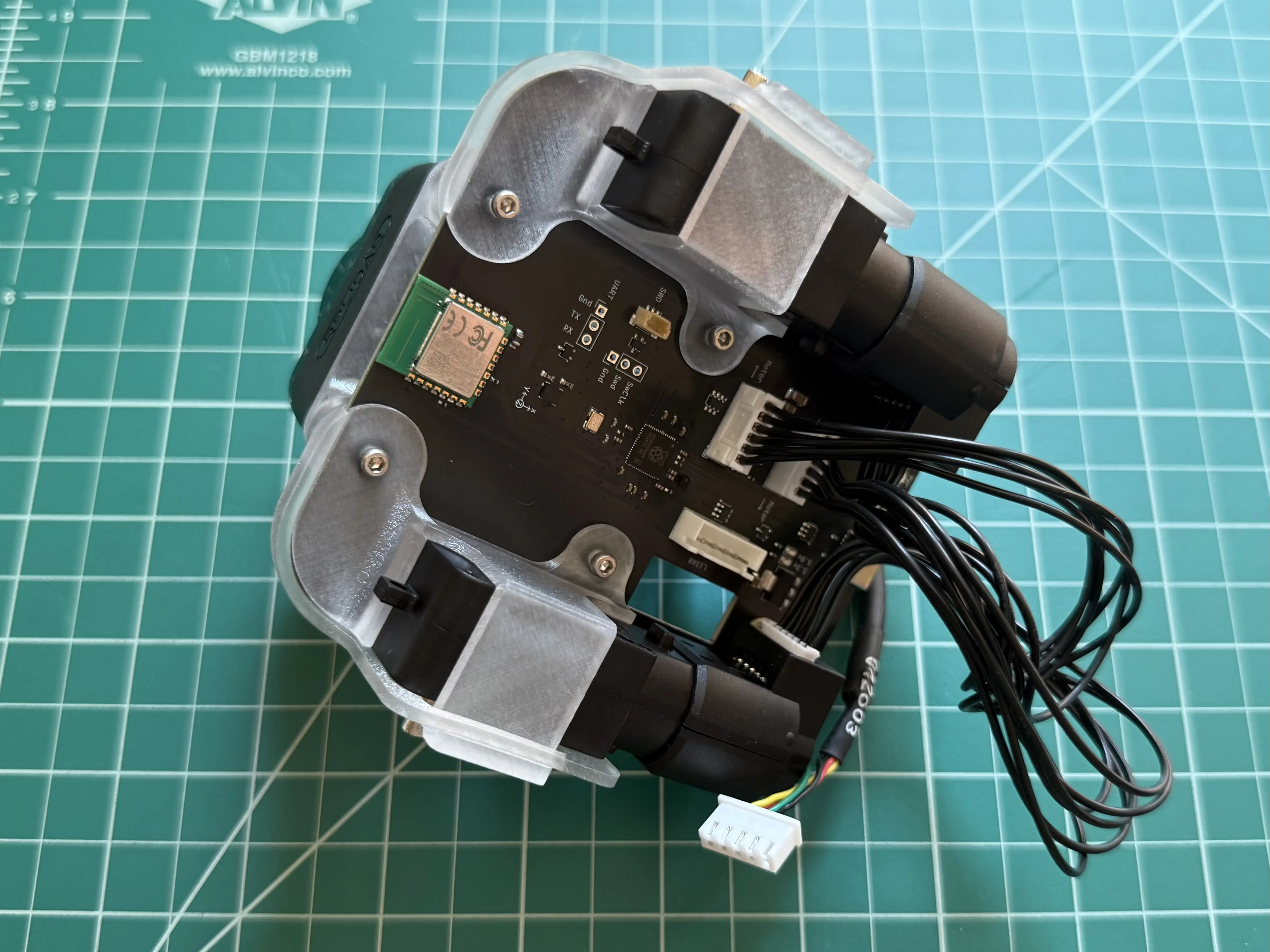
Route the LiDAR’s cable through the hole in the circuit board.
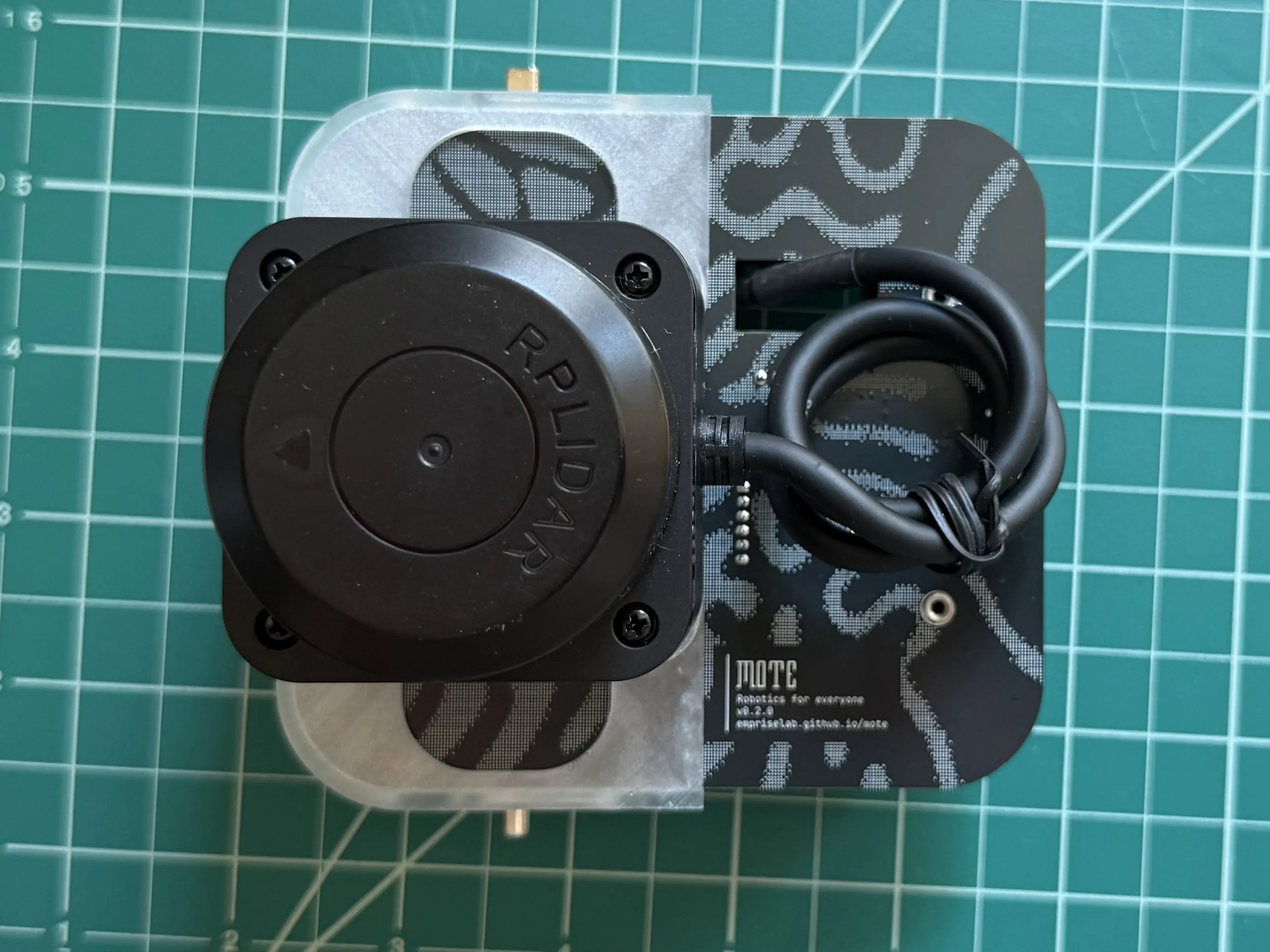
Connect the LiDAR’s cable to the connector on the bottom of the circuit board labeled “LiDAR”.
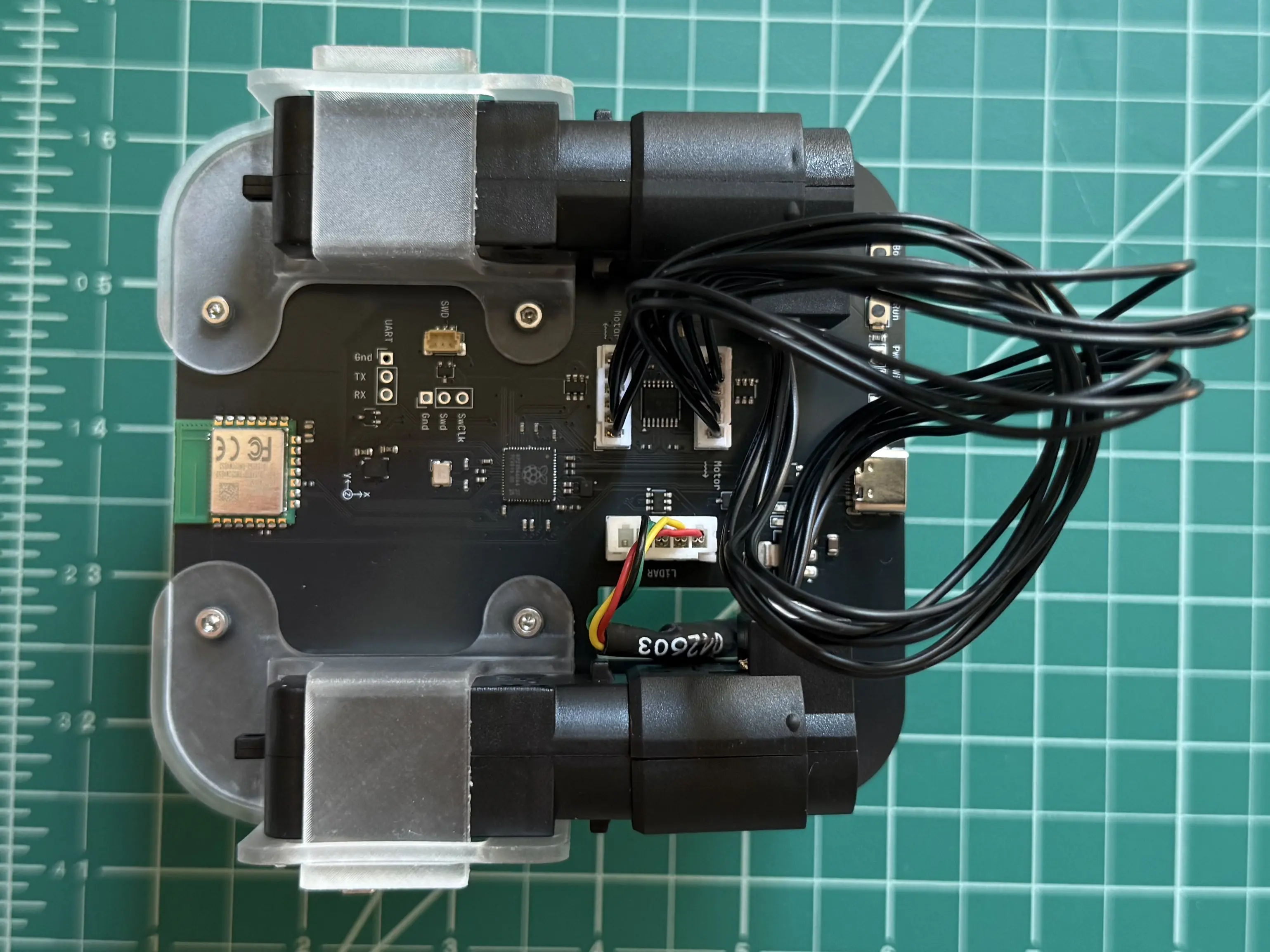
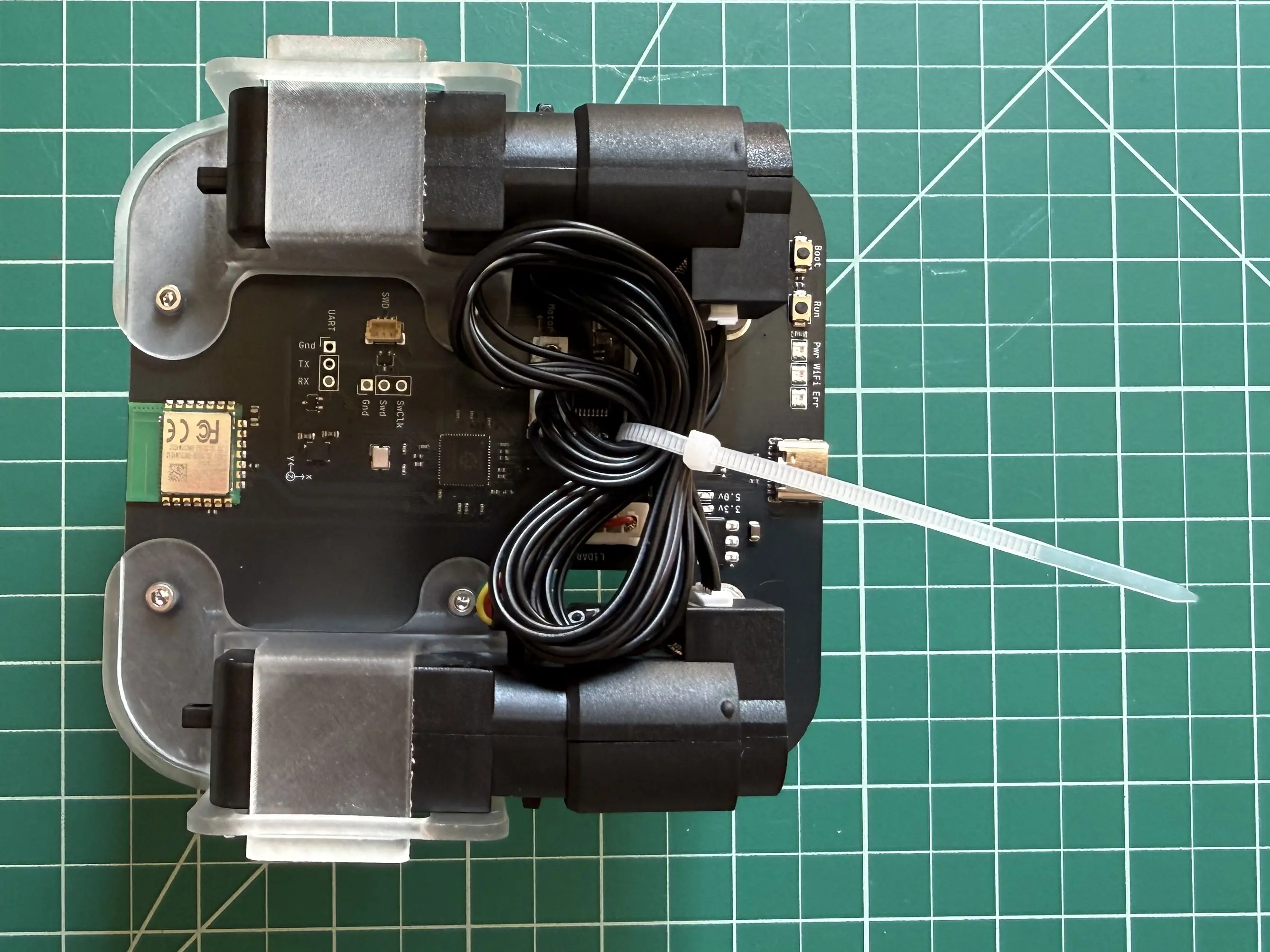
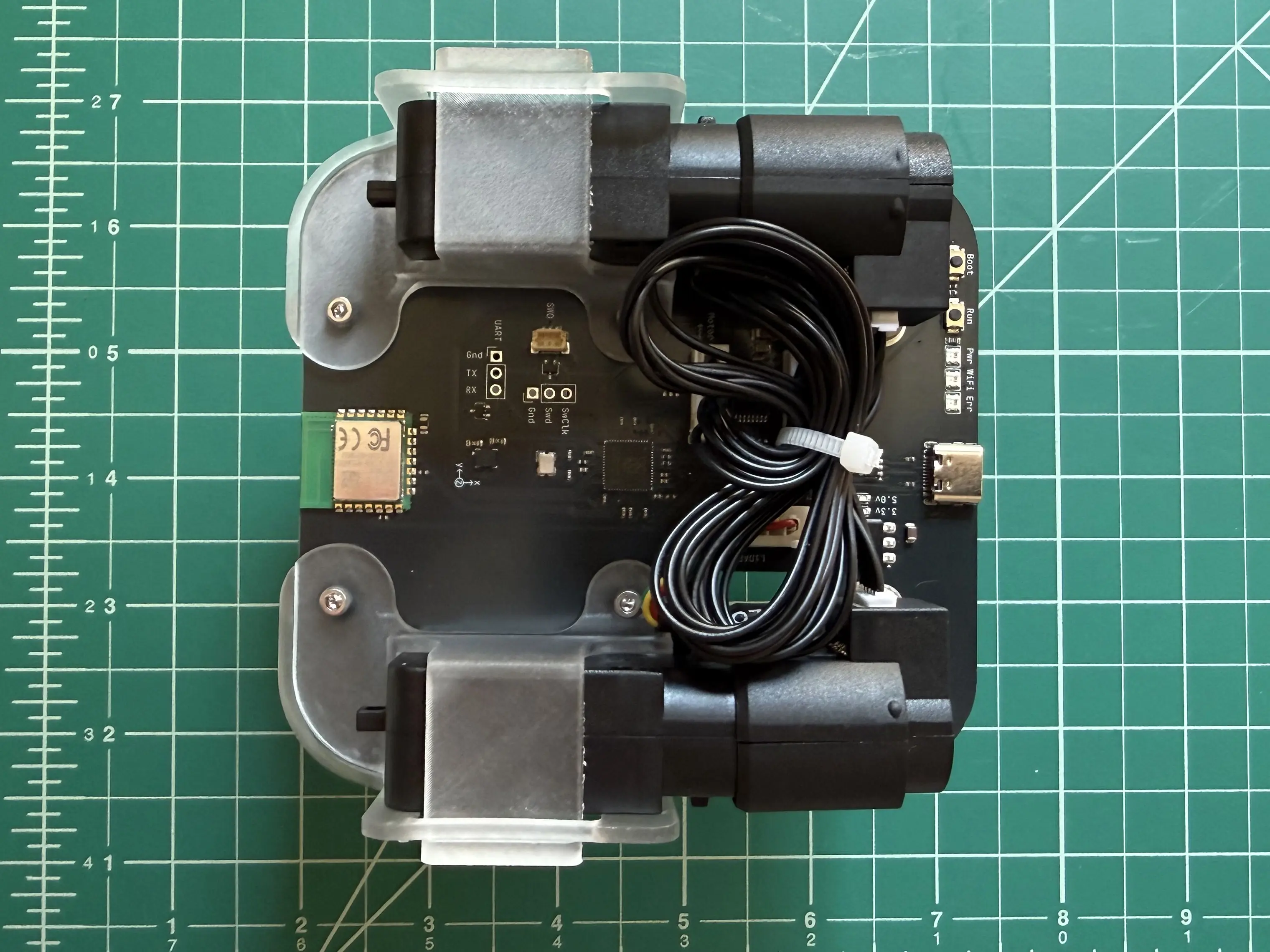
Restrain the motor cables using a cable tie. Trim the cable tie to prevent dragging.
Wheels
Add a wheel spacer to the left motor.
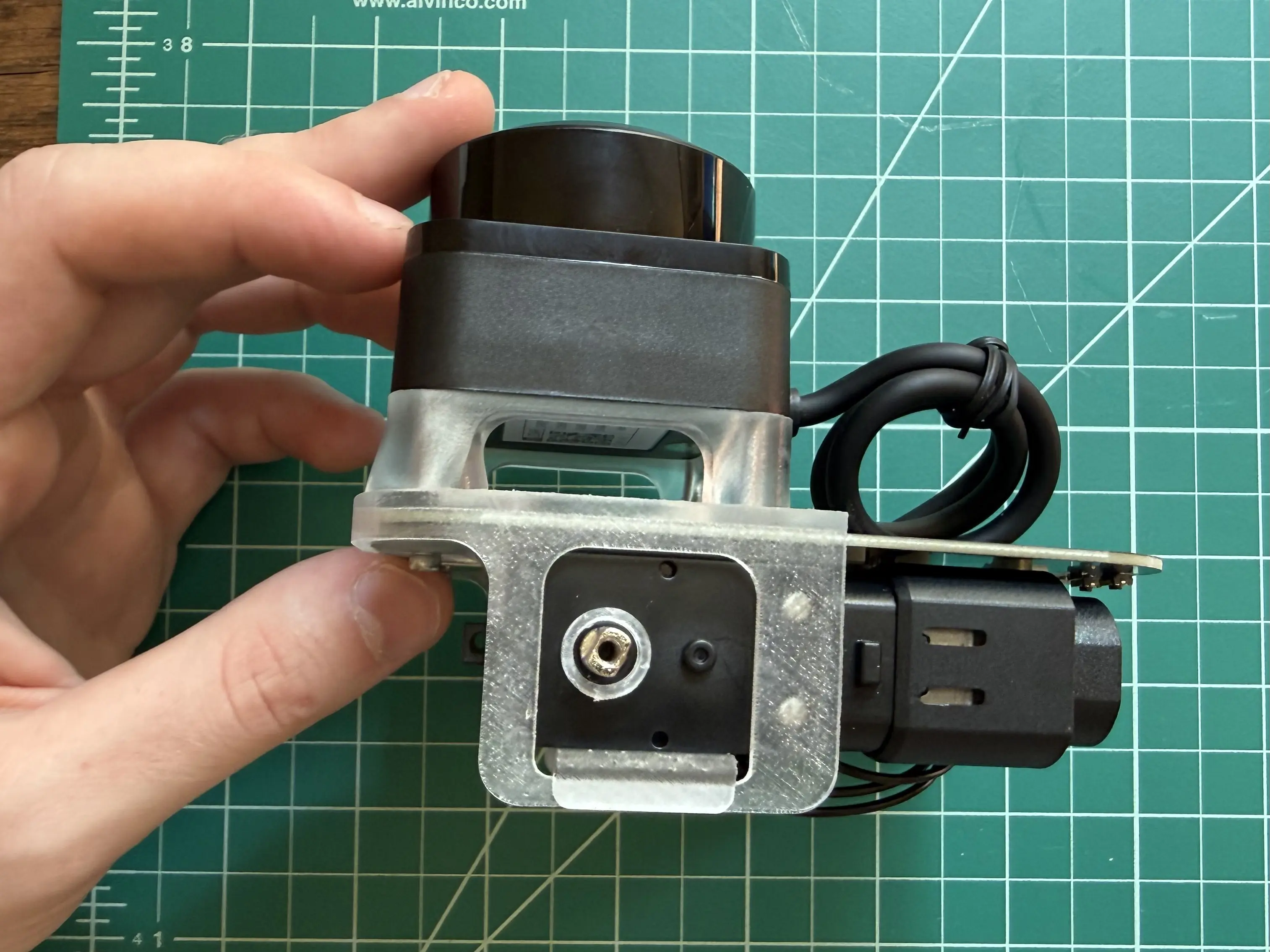
Push the wheel onto the motor shaft.
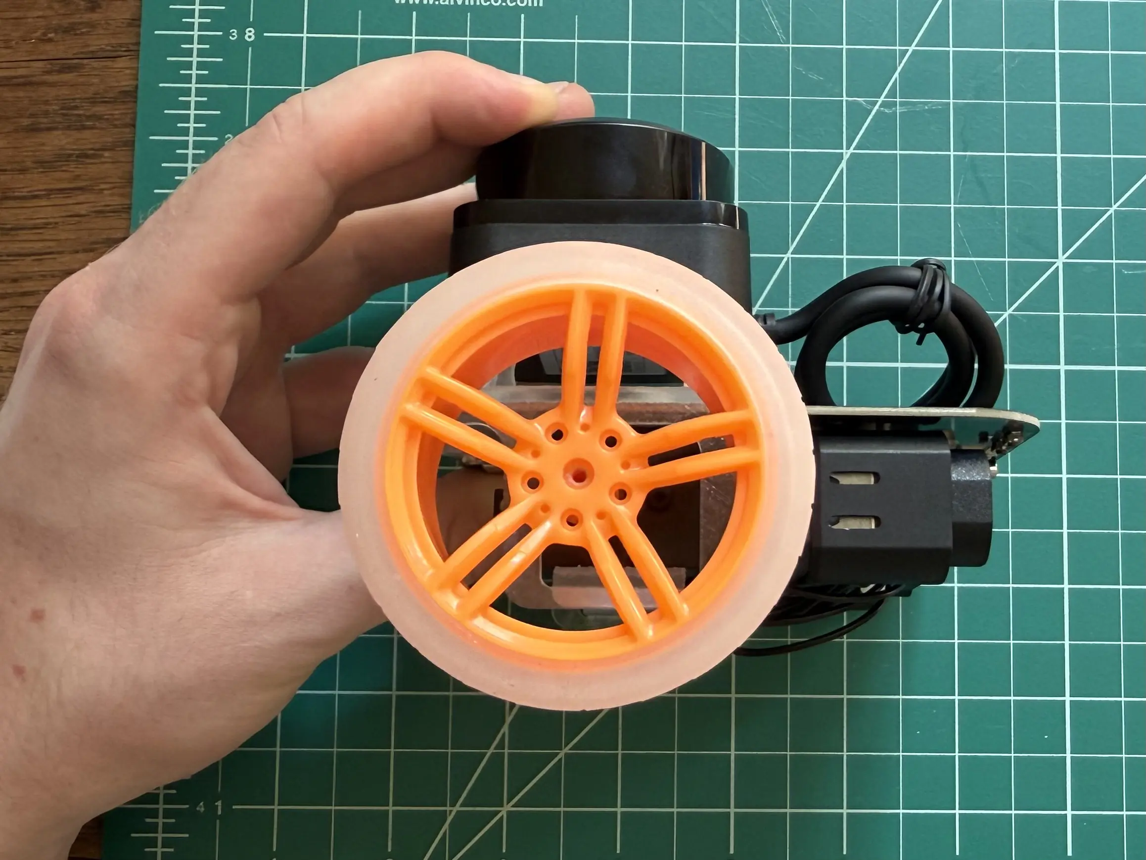
Secure the wheel with a 25mm screw.
Tip
The M2.5 screw must be threaded into the hole on the wheel. You may need to apply some pressure to get the thread started.
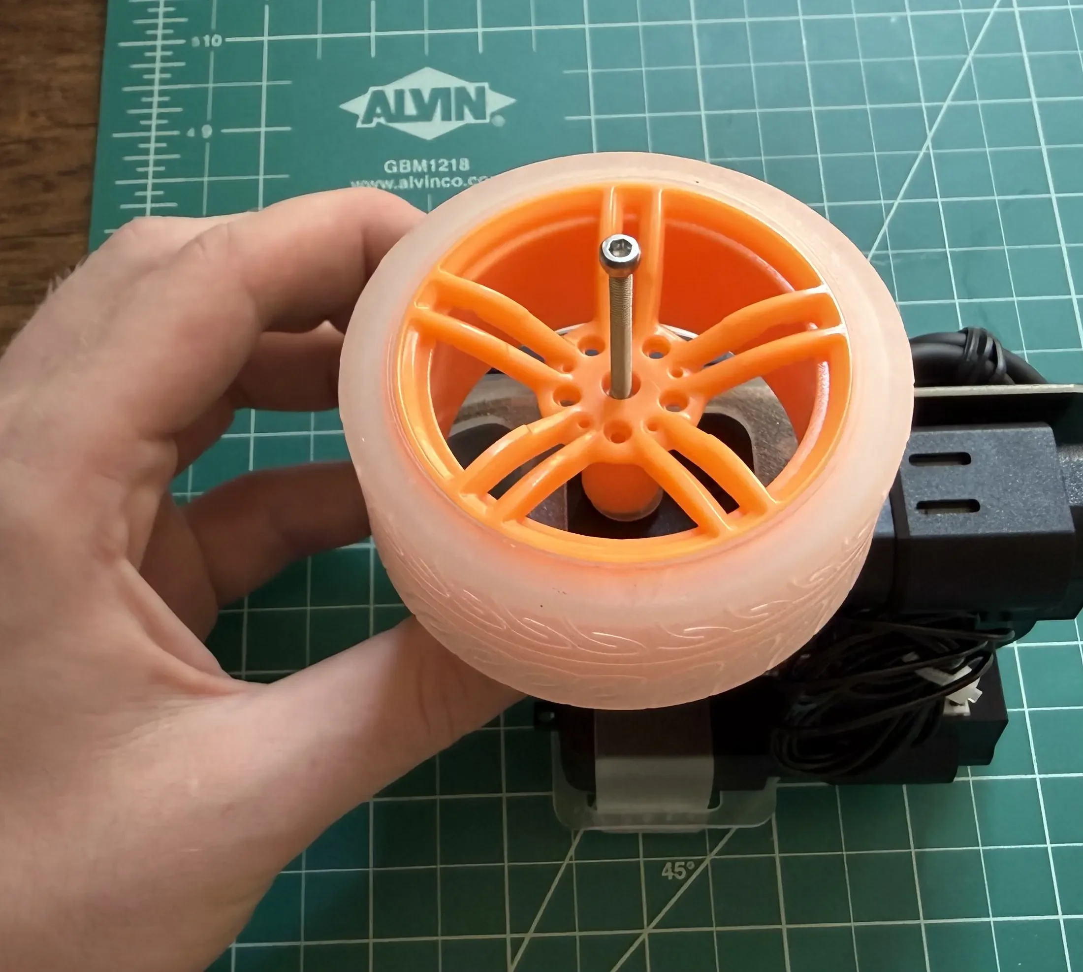
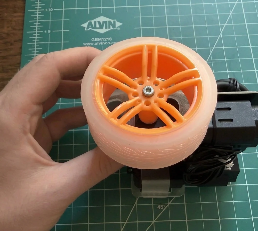
Repeat for the right wheel.
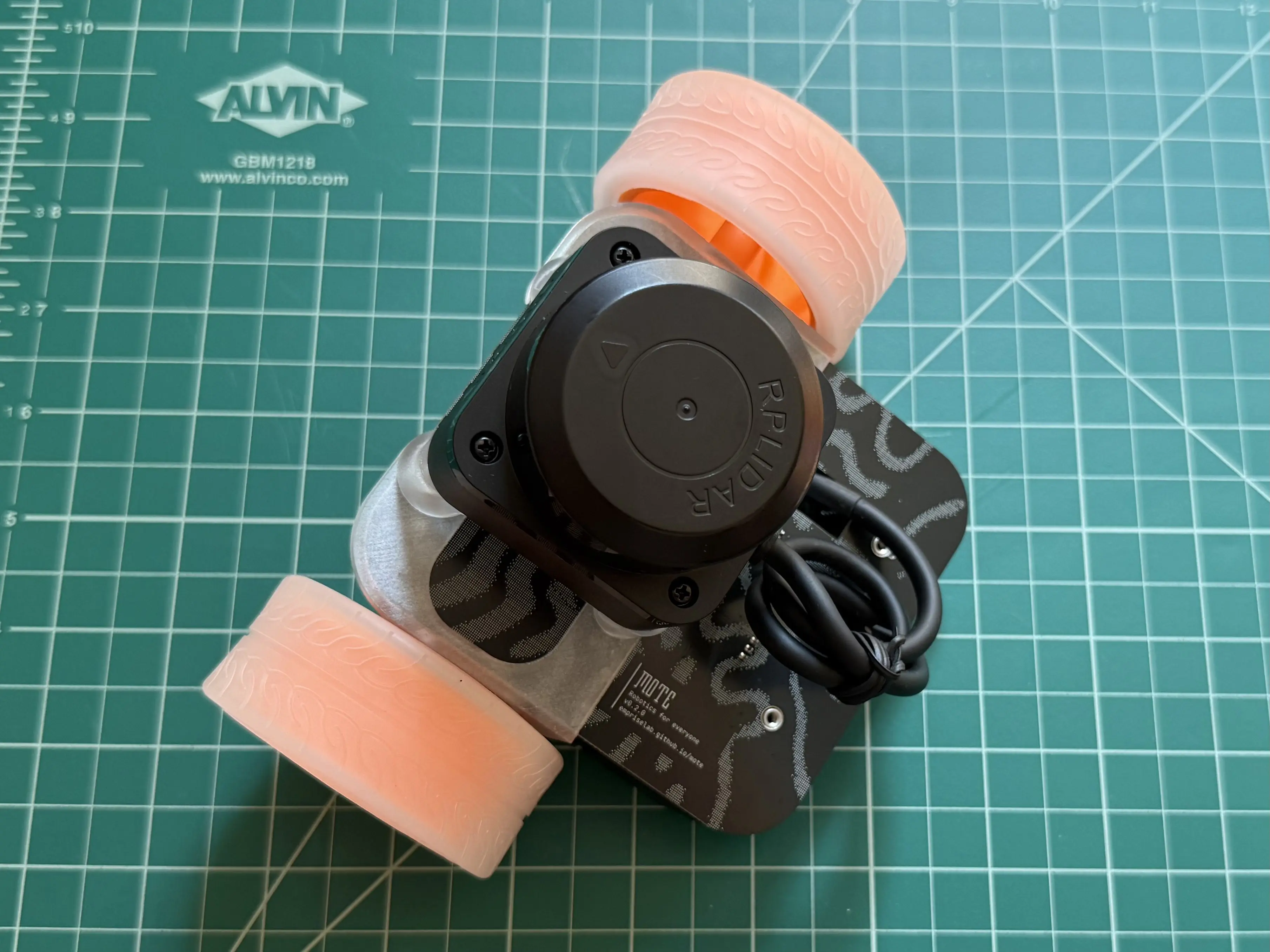
Tail Runner
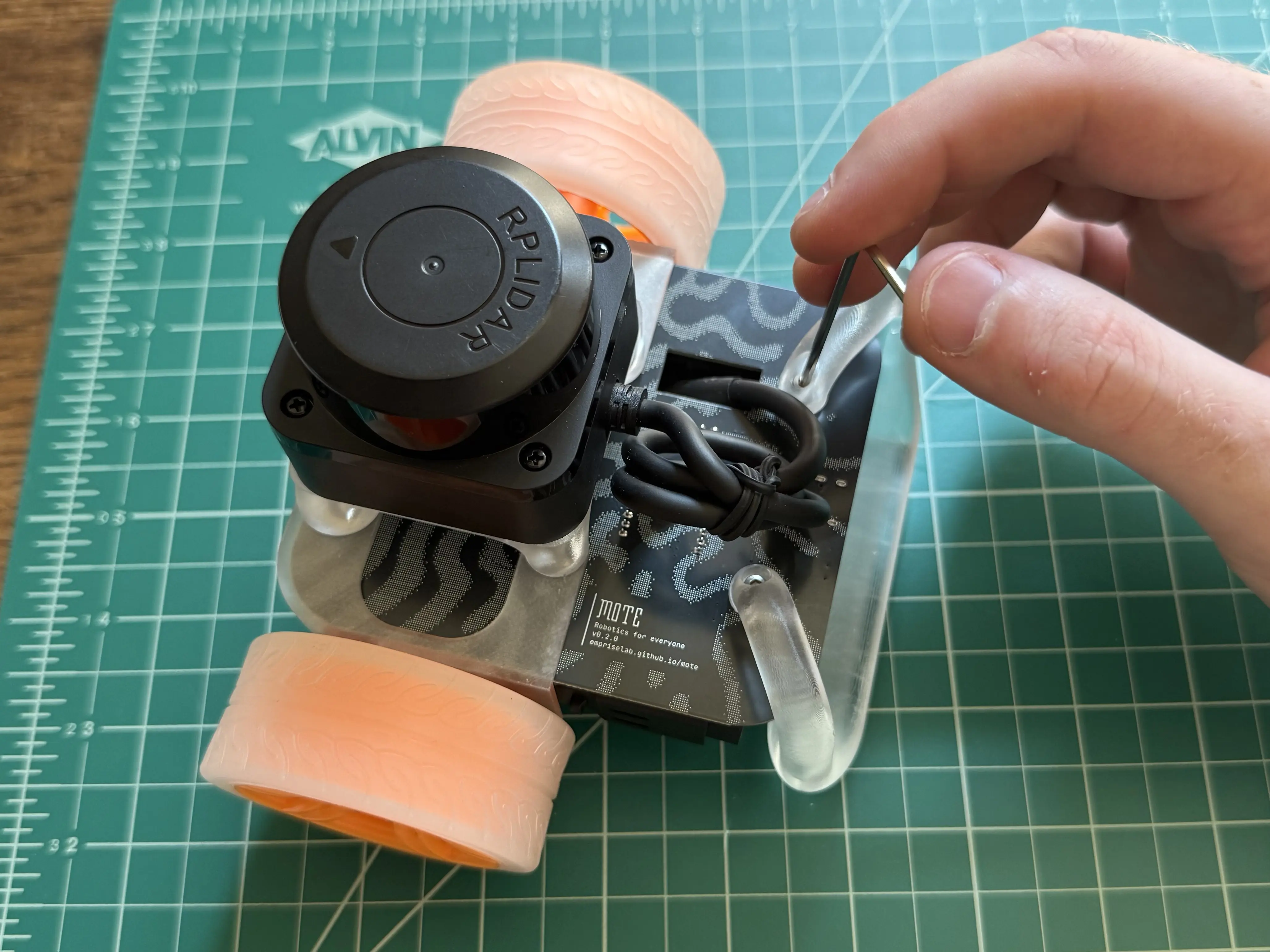
Place a 6mm screw into the hole on the tail runner. Align the screw with the nut on the circuit board, then use the hex key to secure the tail runner to the circuit board. Repeat with the second 6mm screw and hole on the tail runner.
Success
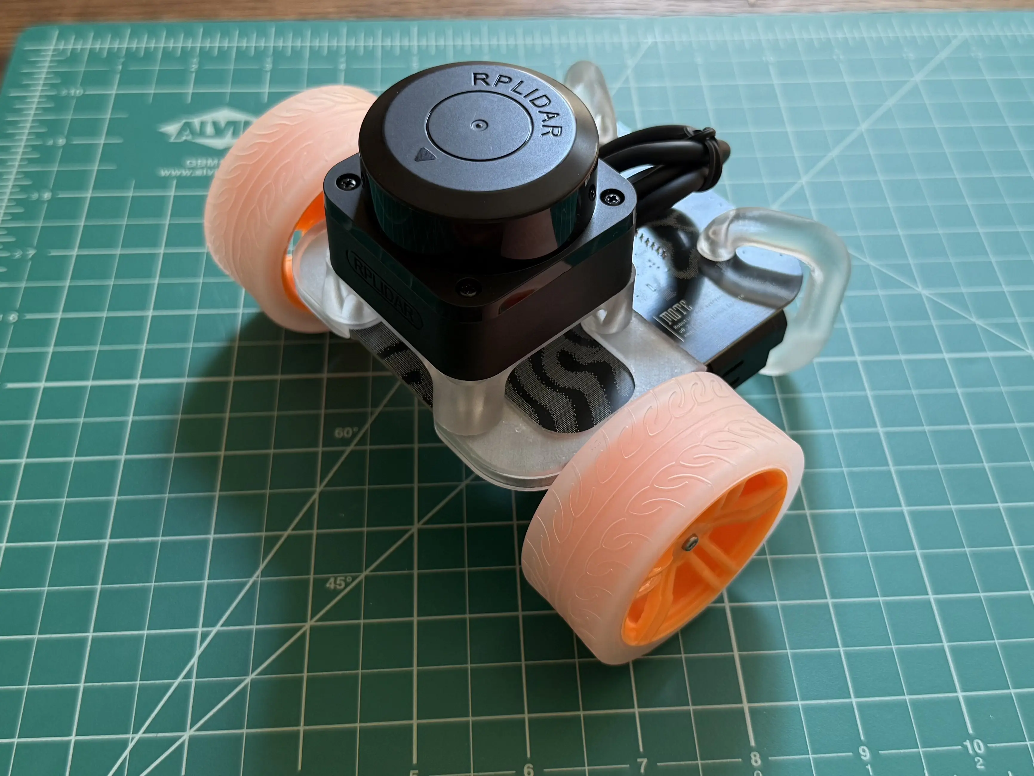
You’ve successfully assembled your Mote!
Next Steps
- Update Firmware - Update your Mote to the latest firmware version