Home
         ┓            ┏
░░░░░▒▒▒▓┃ ┳┳┓┏┓┏┳┓┏┓ ┃▓▒▒▒░░░░░
░░░░░▒▒▒▓┃ ┃┃┃┃┃ ┃ ┣  ┃▓▒▒▒░░░░░
░░░░░▒▒▒▓┃ ┛ ┗┗┛ ┻ ┗┛ ┃▓▒▒▒░░░░░
         ┛            ┗
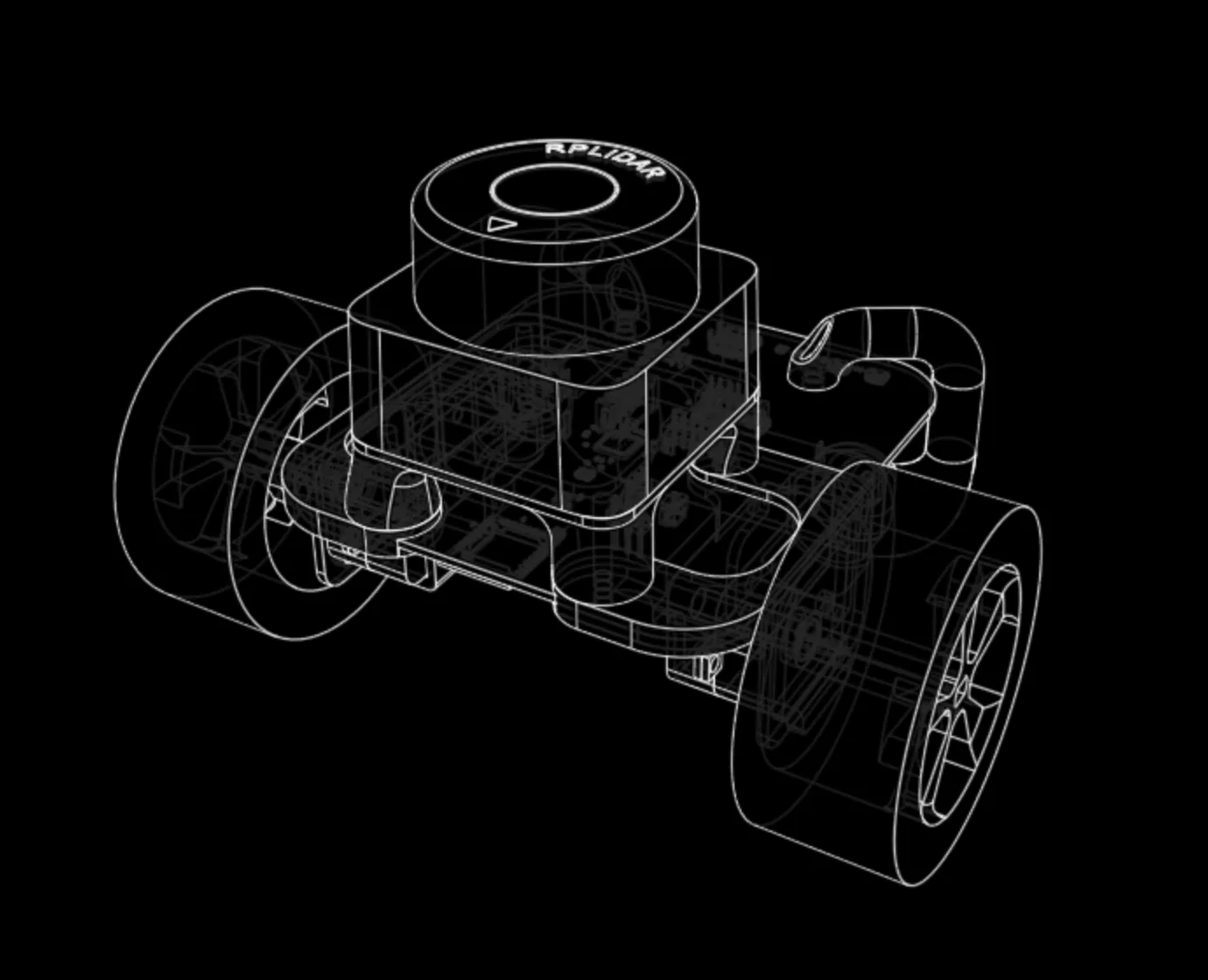
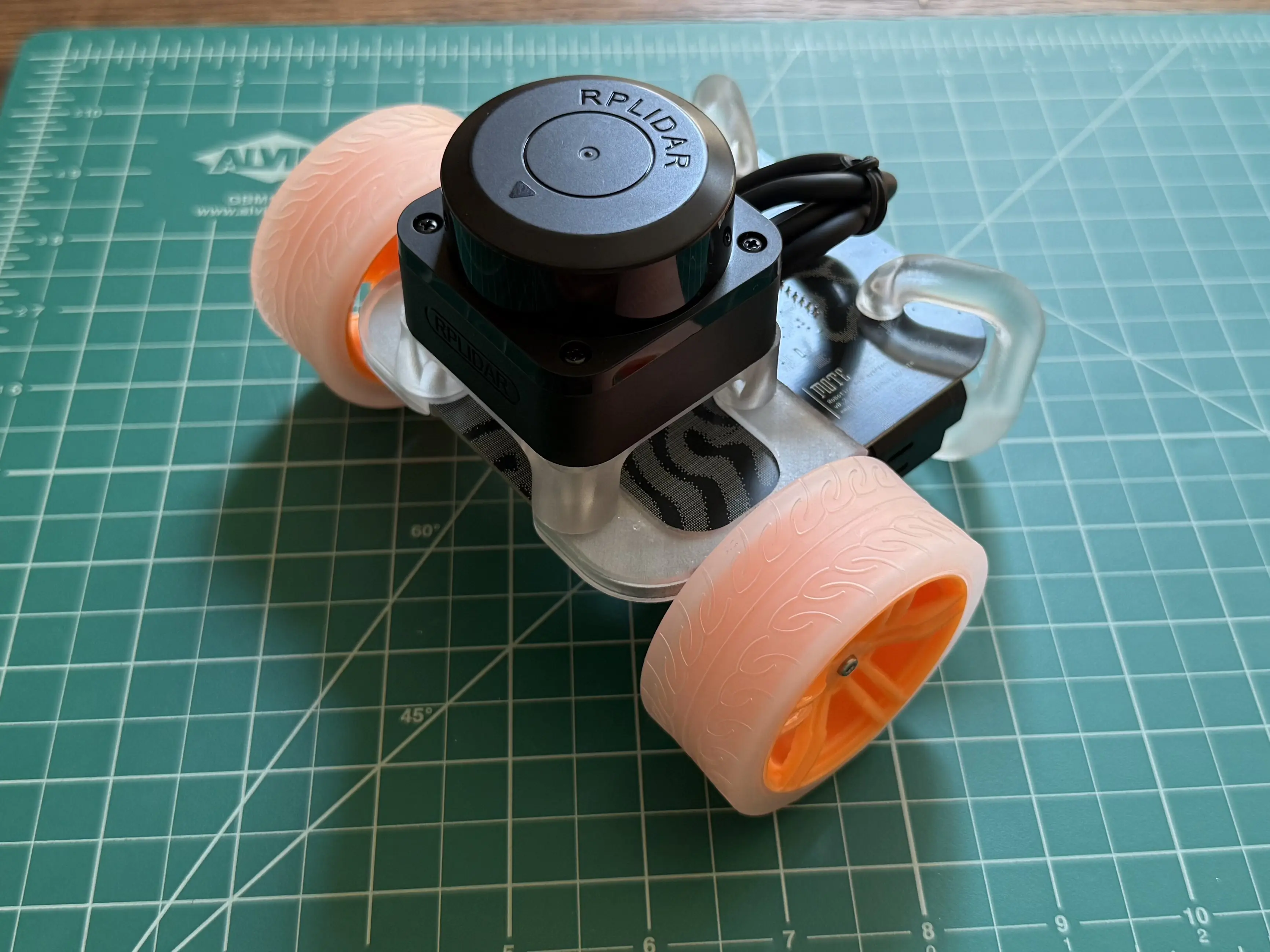
The low-cost, high-reliablity mobile robot for hands-on robotics education.
Highlights
- LiDAR, IMU, and wheel position data streamed over WiFi
- Polished SDKs for ROS, ROS2, Python and Rust
- Wide cross-platform support
- Open source firmware, software, and hardware
- Only $100
Getting Started
Assemble your kit if you already have the parts, or checkout the hardware sourcing guide if you’re starting from scratch.
Kit Assembly
In this tutorial you will assemble your Mote. It should take around 15 minutes.
Gather Parts
First, check that you have the required parts. Missing something? Check out the sourcing guide.
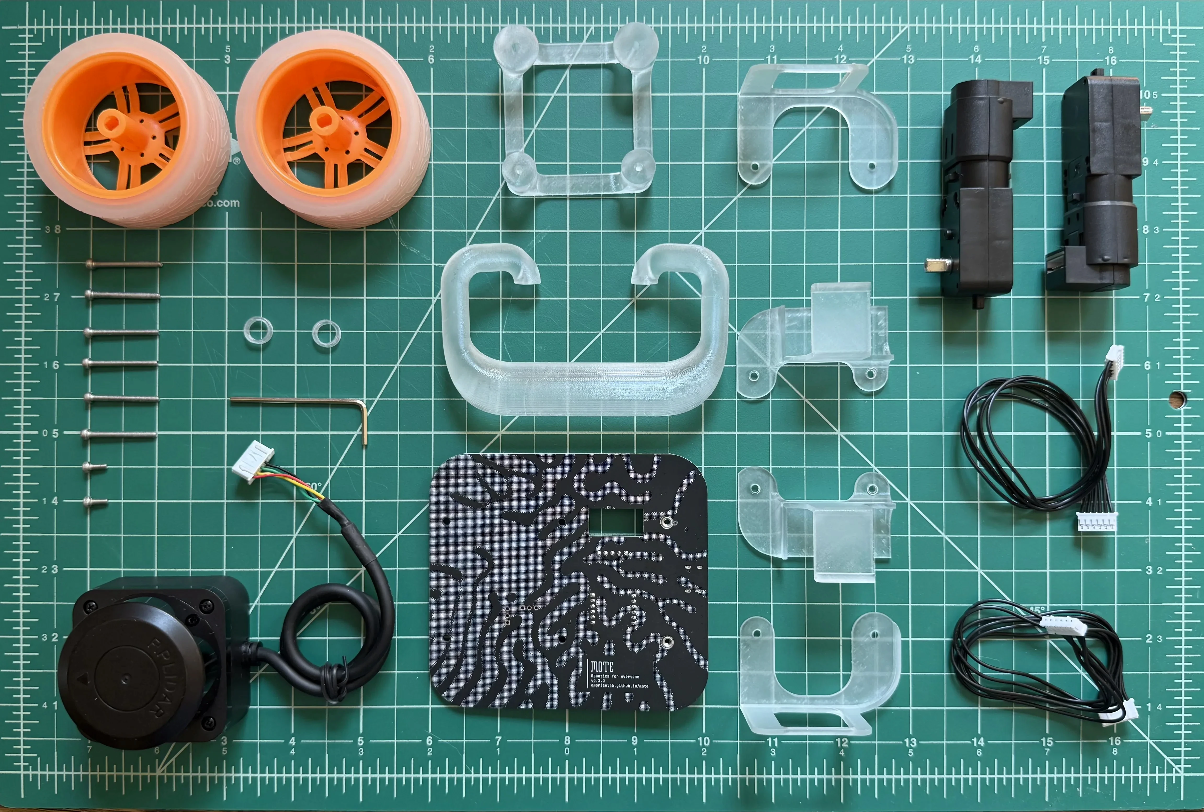
| Item | Quantity | Picture |
|---|---|---|
| Circuit Board | 1 | 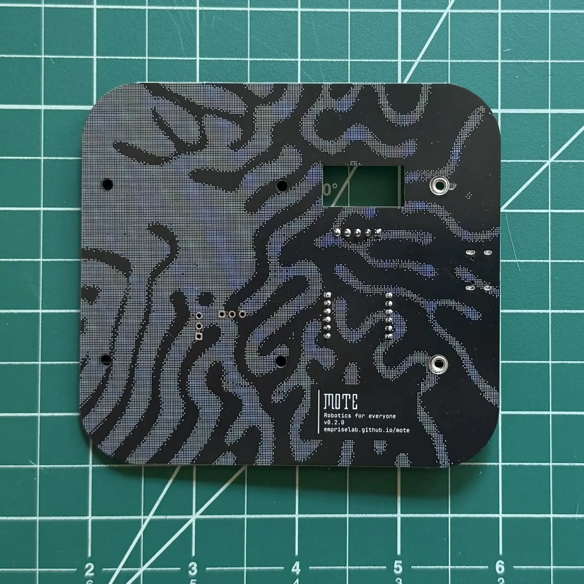 |
| Left Motor Mount | 1 | 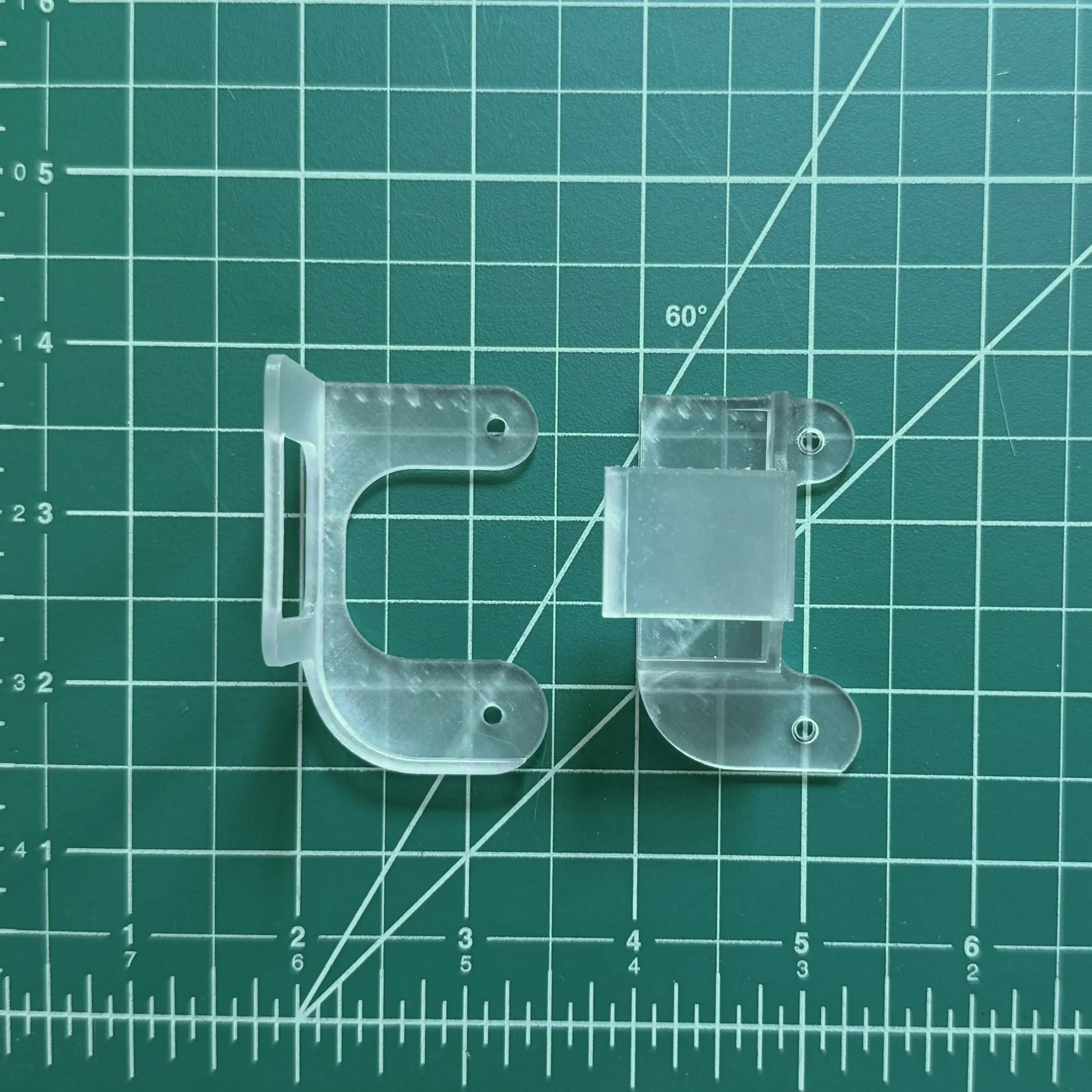 |
| Right Motor Mount | 1 | 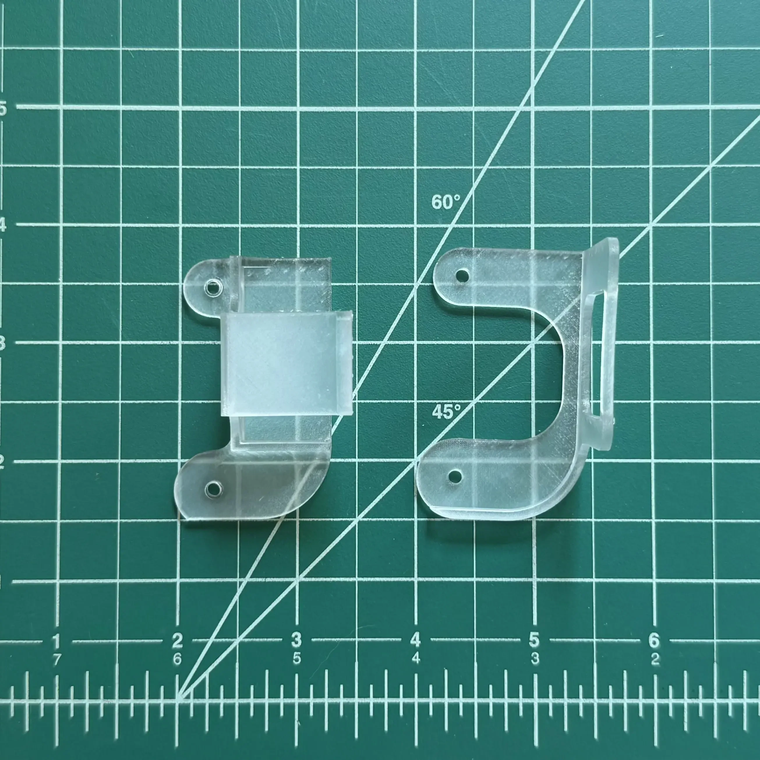 |
| Tail Runner | 1 | 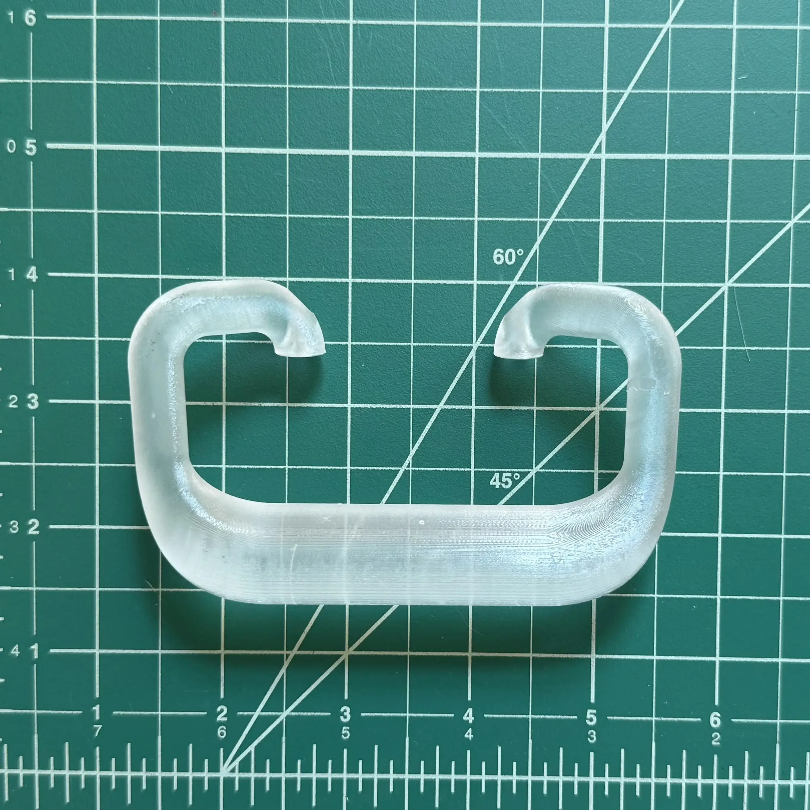 |
| LiDAR Mount | 1 | 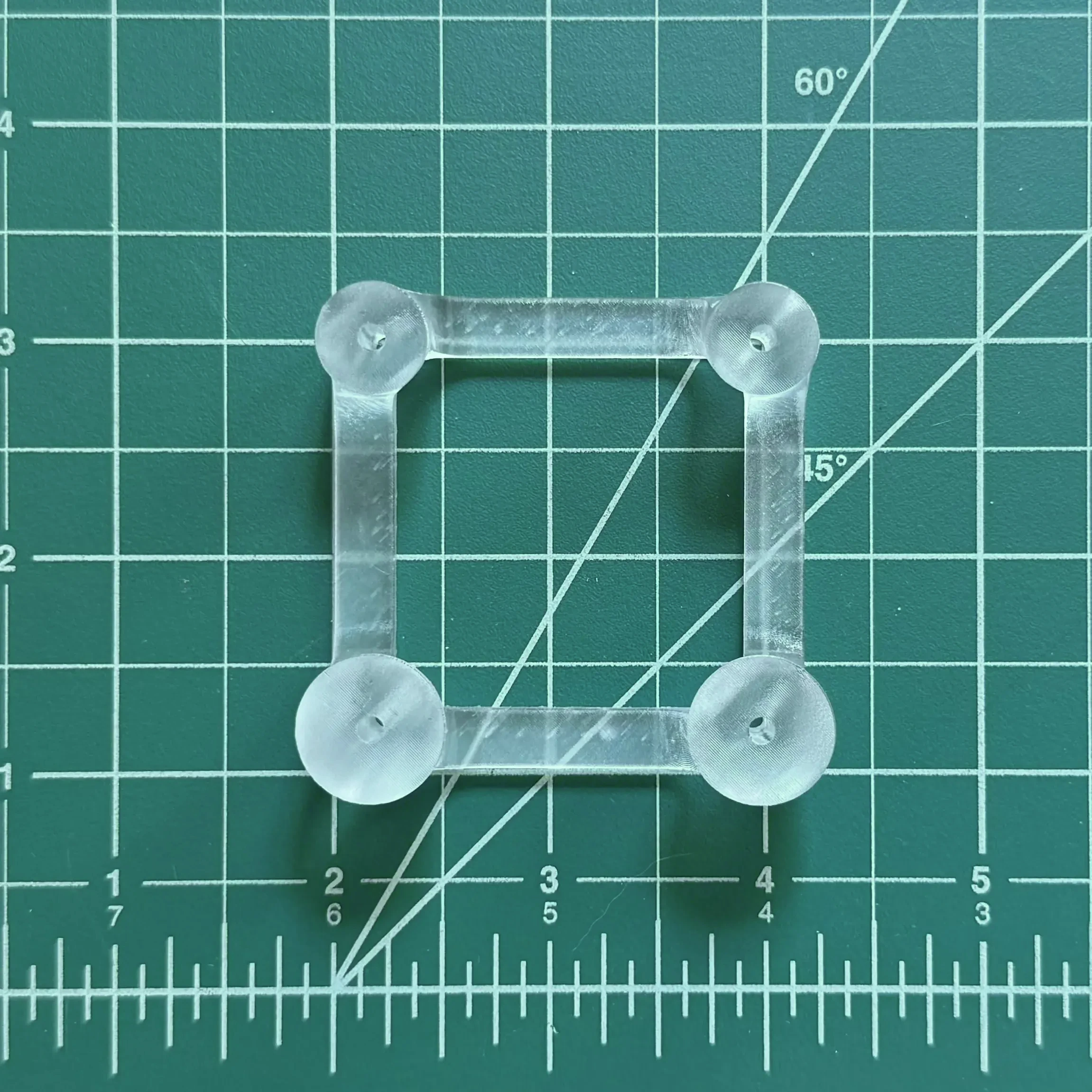 |
| Wheel Spacers | 2 | 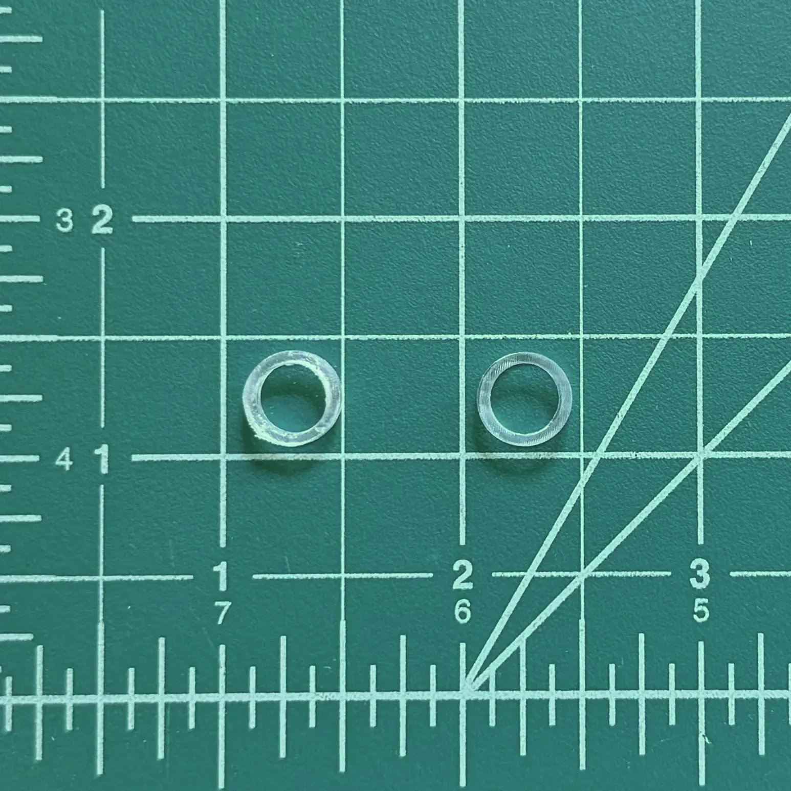 |
| LiDAR | 1 | 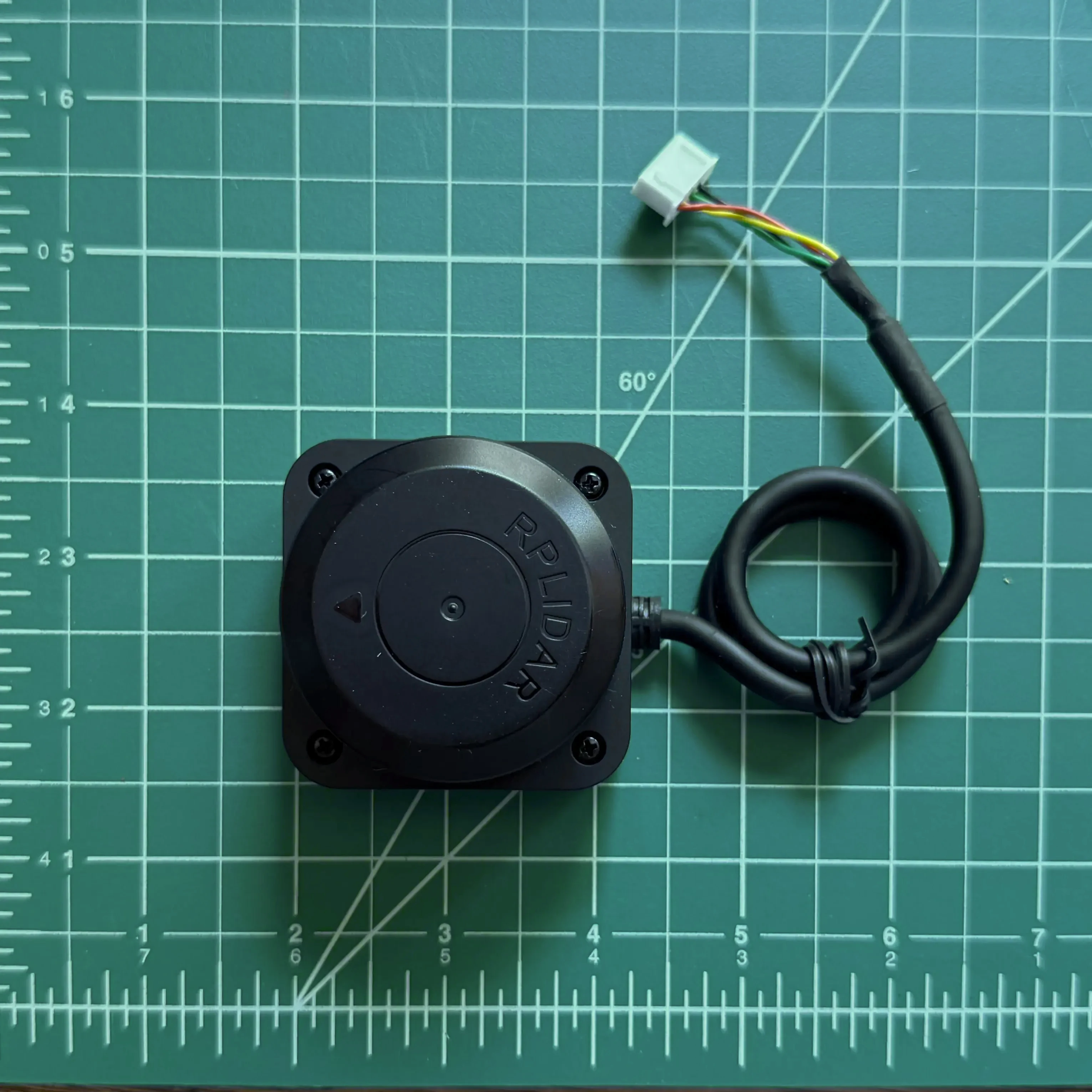 |
| Orange Wheel | 2 | 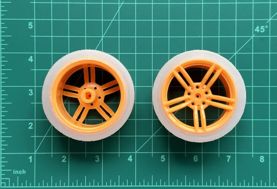 |
| Motor with Encoder | 2 | 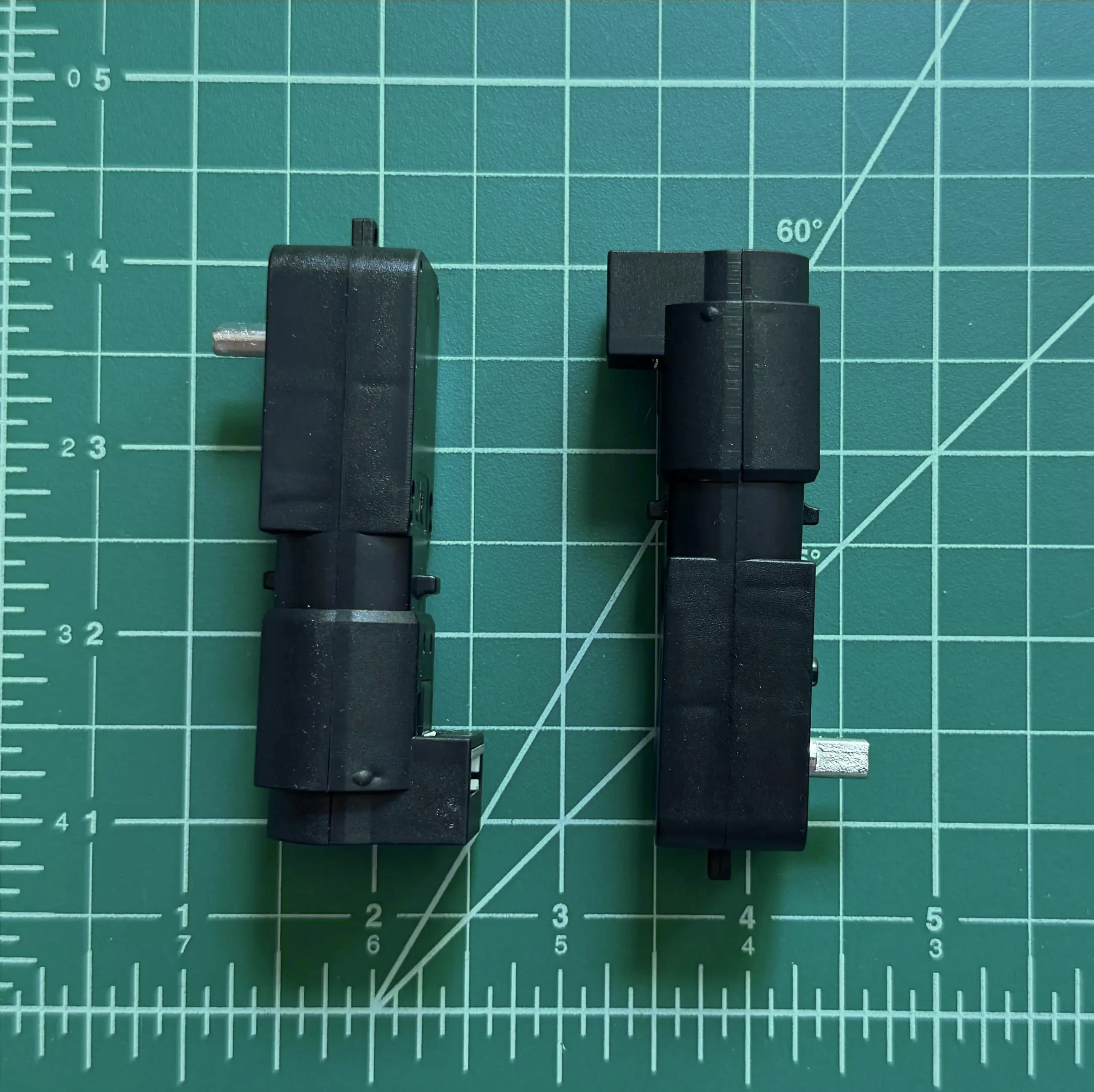 |
| 25mm M2.5 Hex Head Machine Screws | 6 | 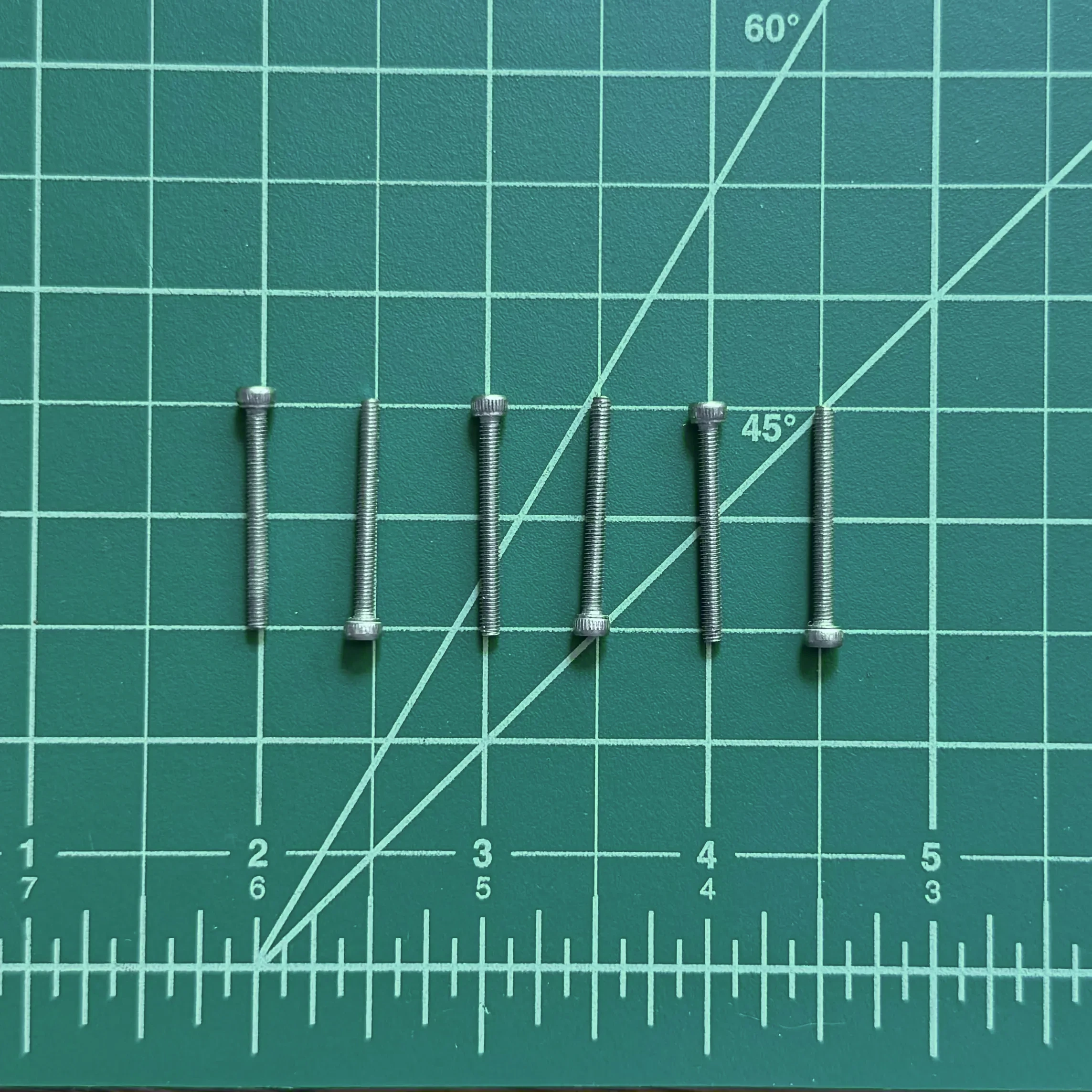 |
| 6mm M2.5 Hex Head Machine Screws | 2 | 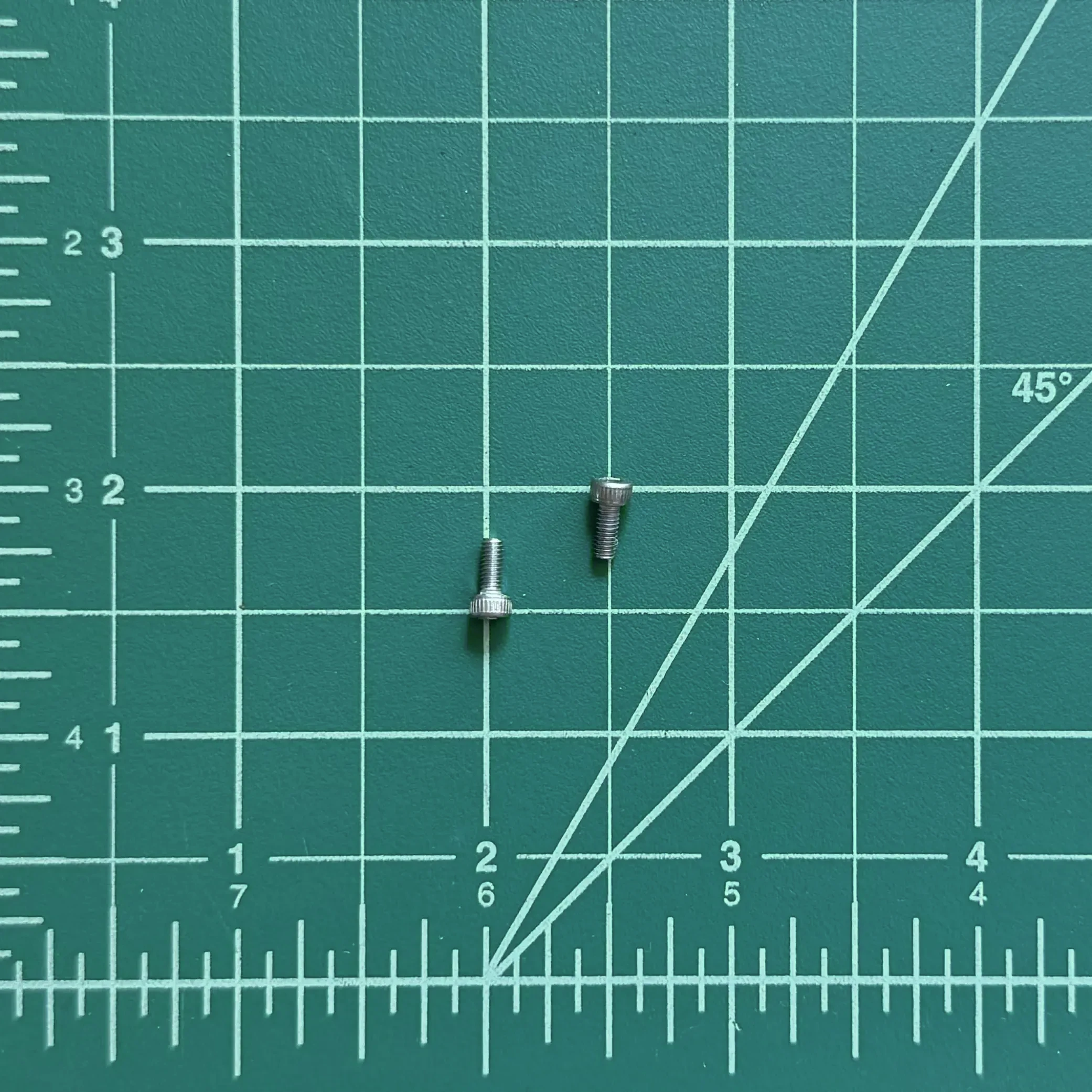 |
| 2mm Hex Key | 1 | 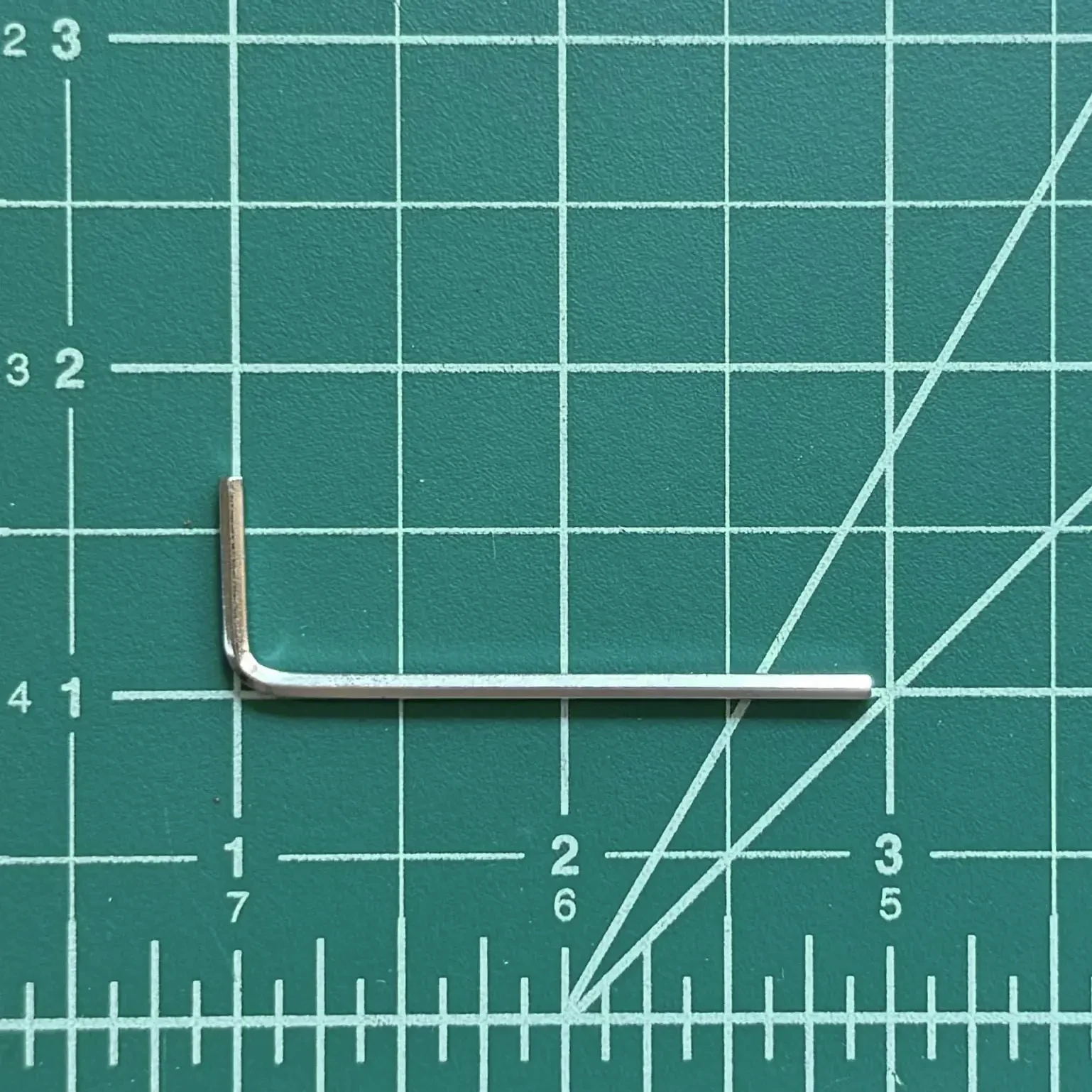 |
| USB-C to C Cable | 1 | 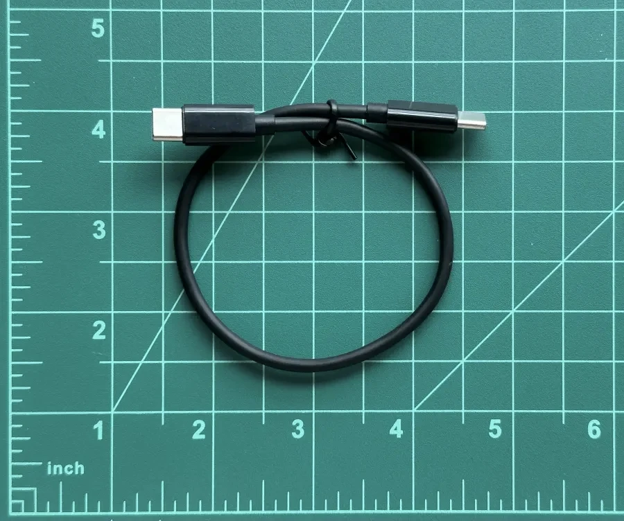 |
| 5000 mAh USB Portable Battery | 1 | 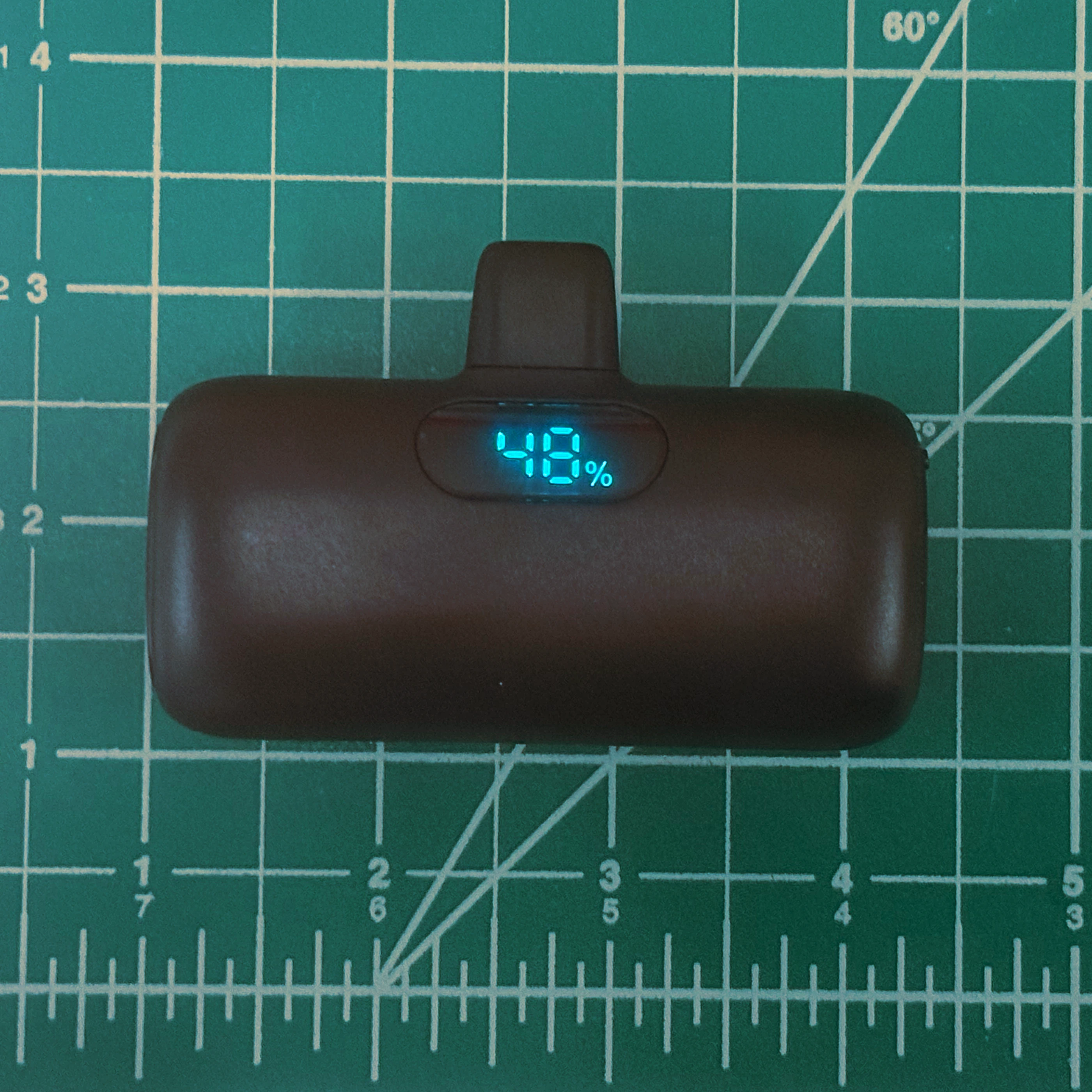 |
Motor Subassembly
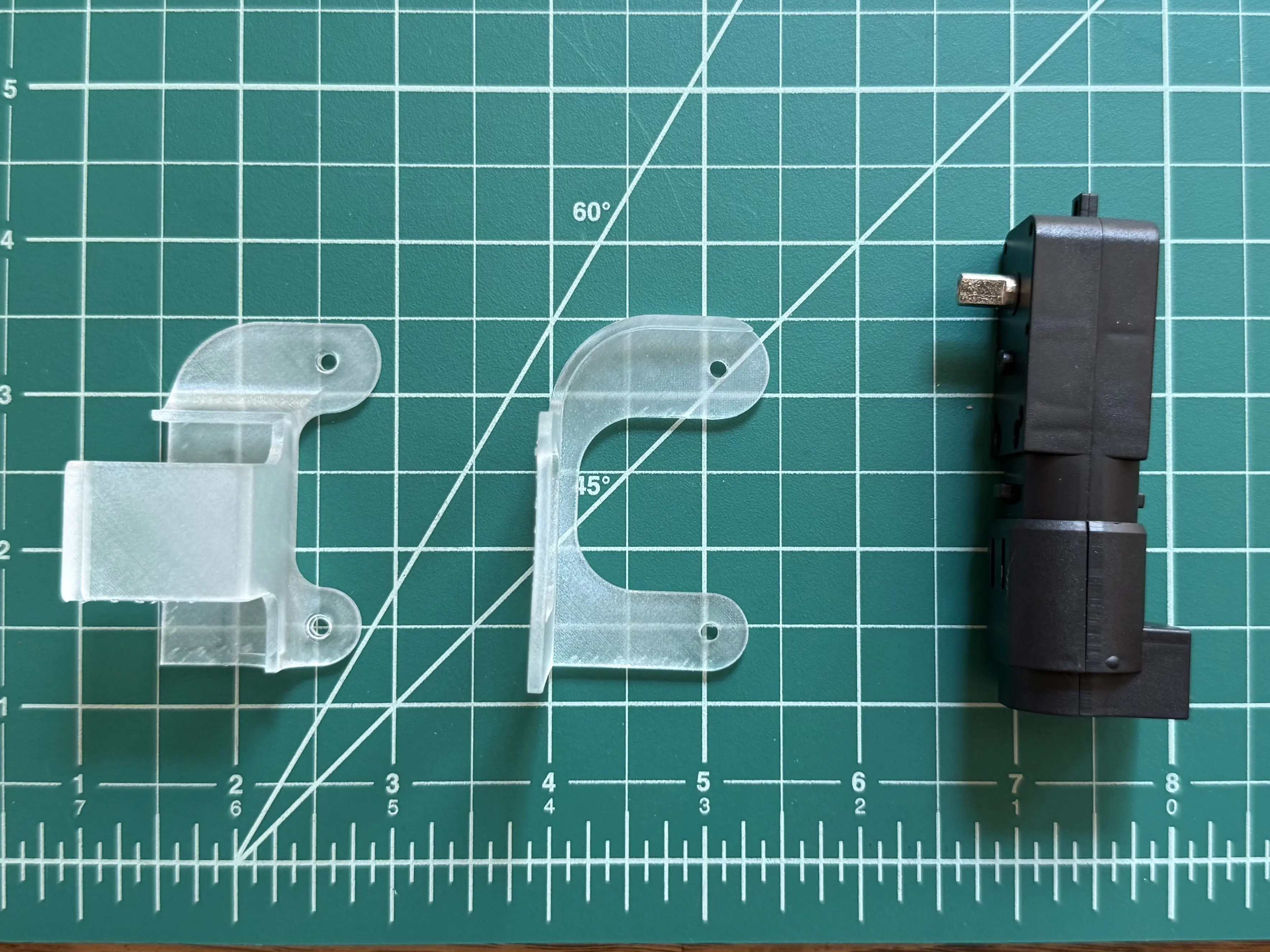
Place the motor into the bottom half of the motor mount. Ensure that the motor is seated in the pocket of the mount.
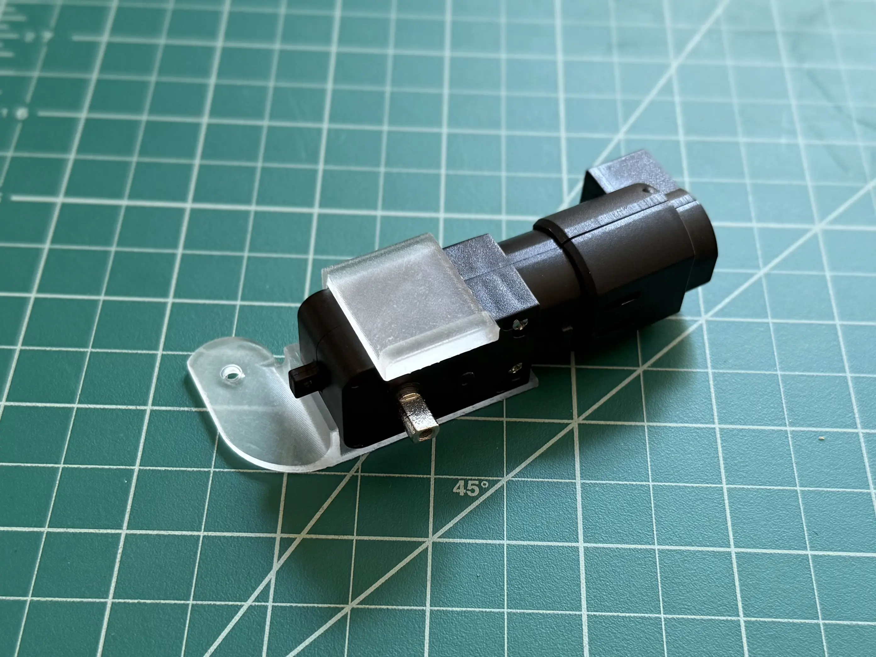
Connect the top side of the motor mount to the bottom side, securing the motor.

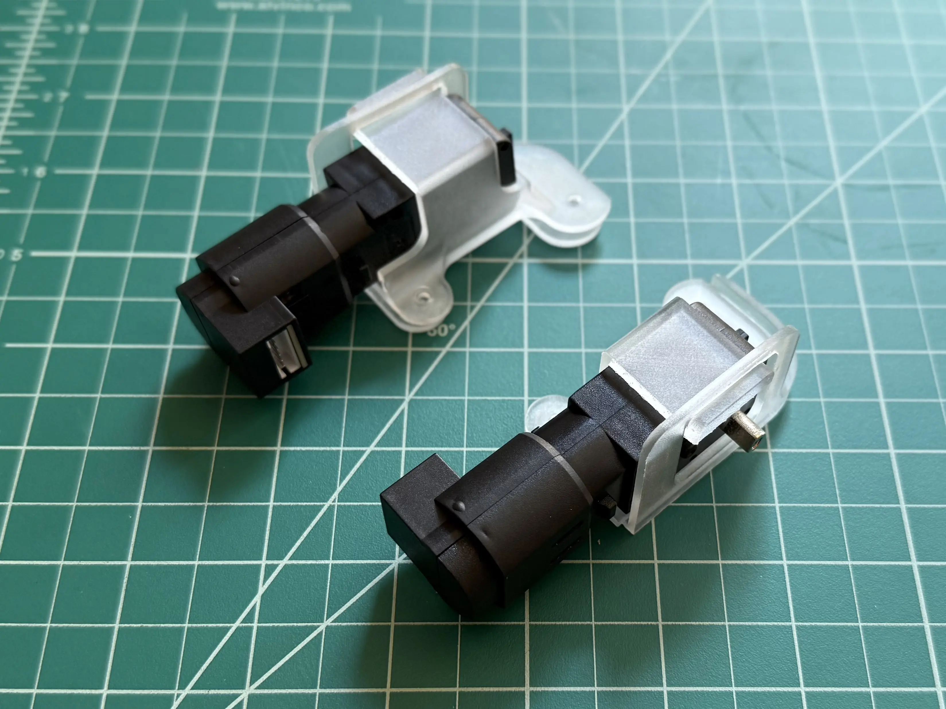
Repeat for the left side motor mount.
Body Assembly
Slide the circuit board between the two halves of the motor mounts, aligning the holes in the mounts with those in the circuit board.
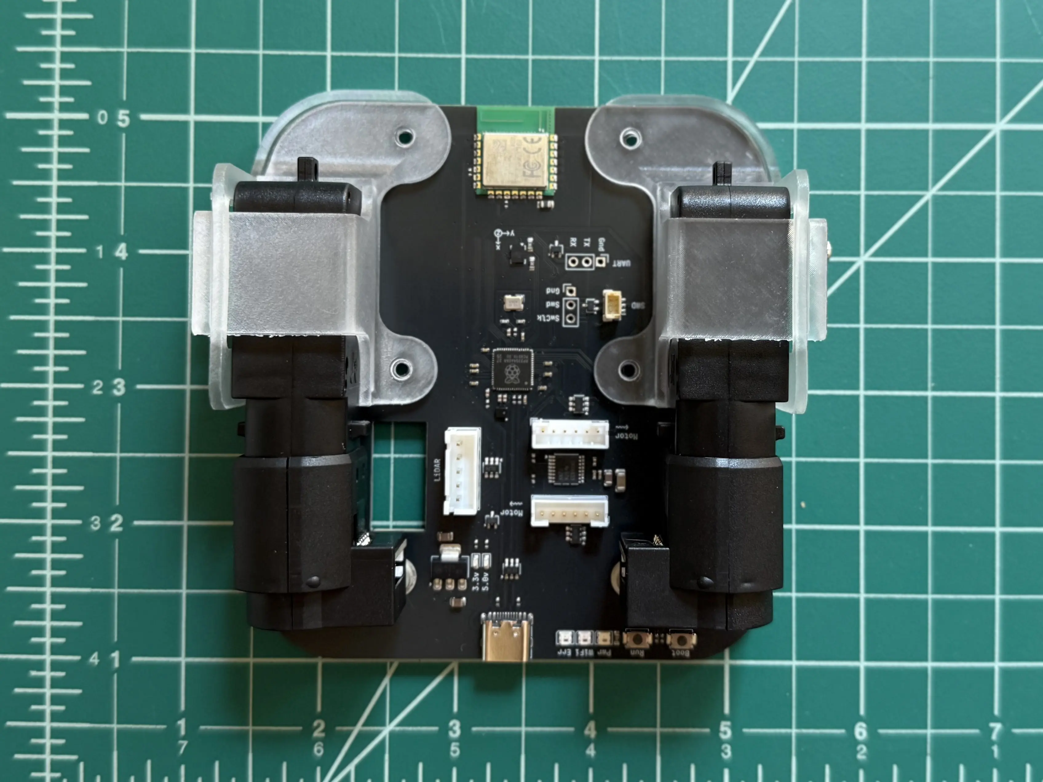
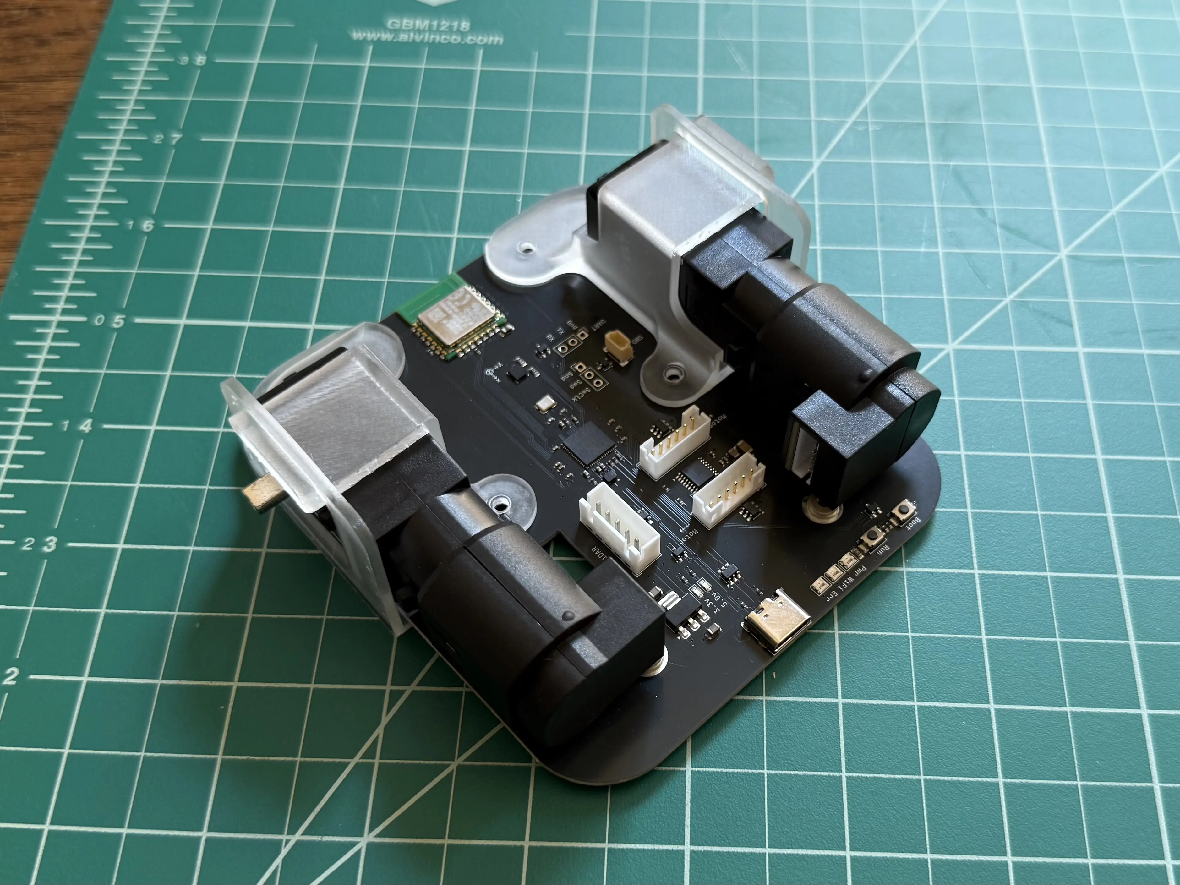
Insert the 25mm screws through the holes in the motor mounts and circuit board.
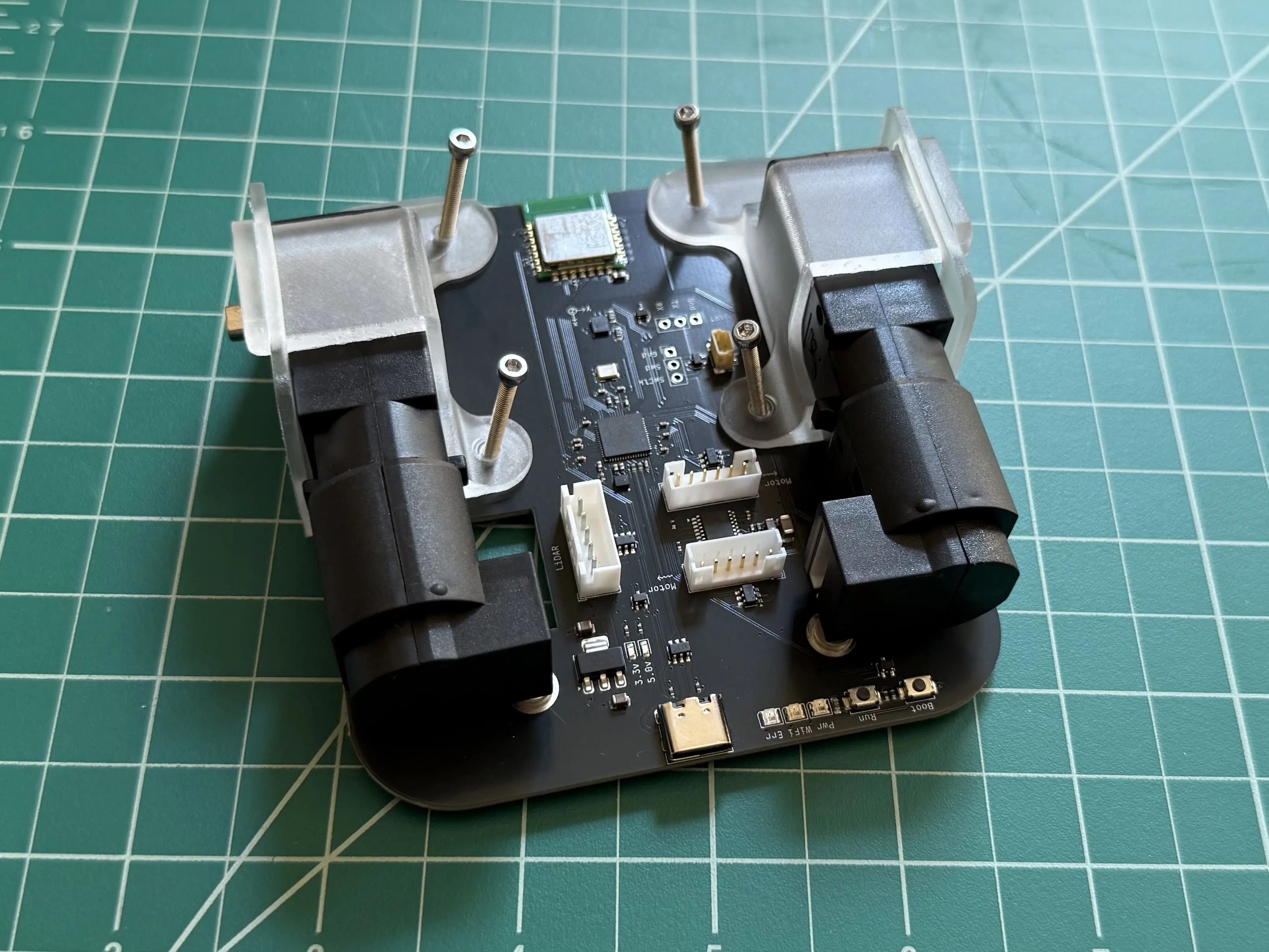
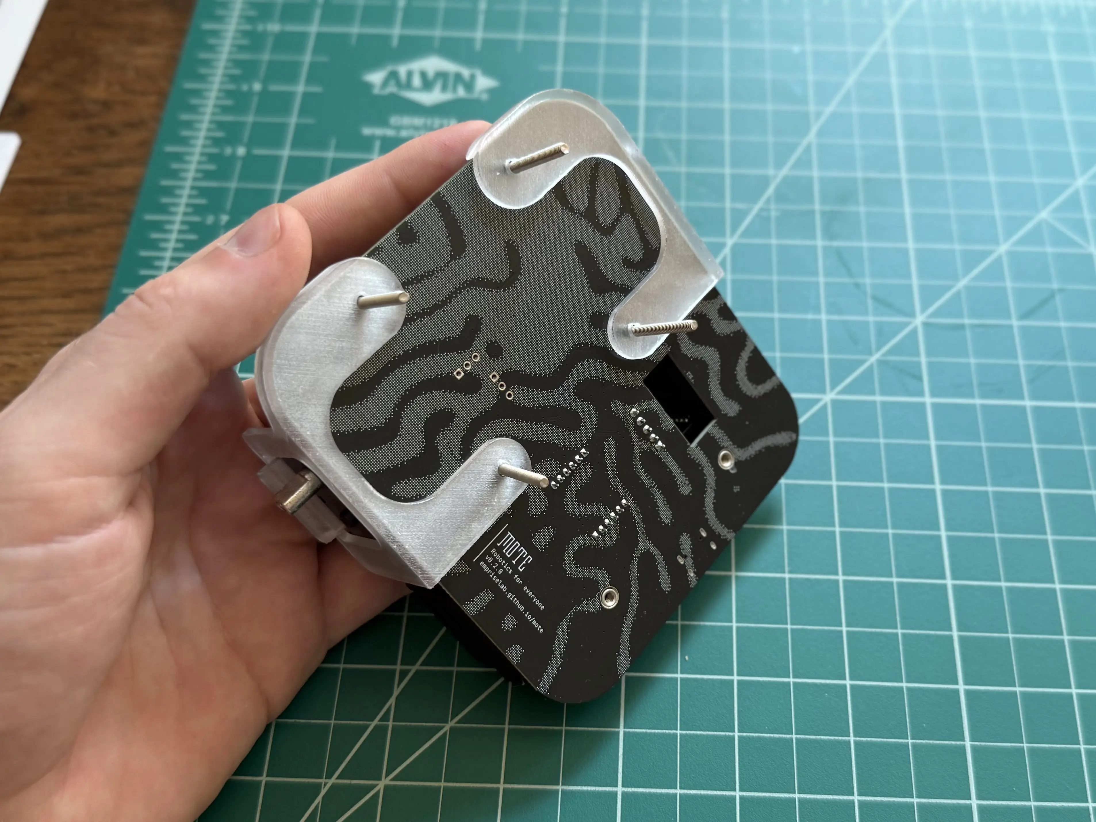
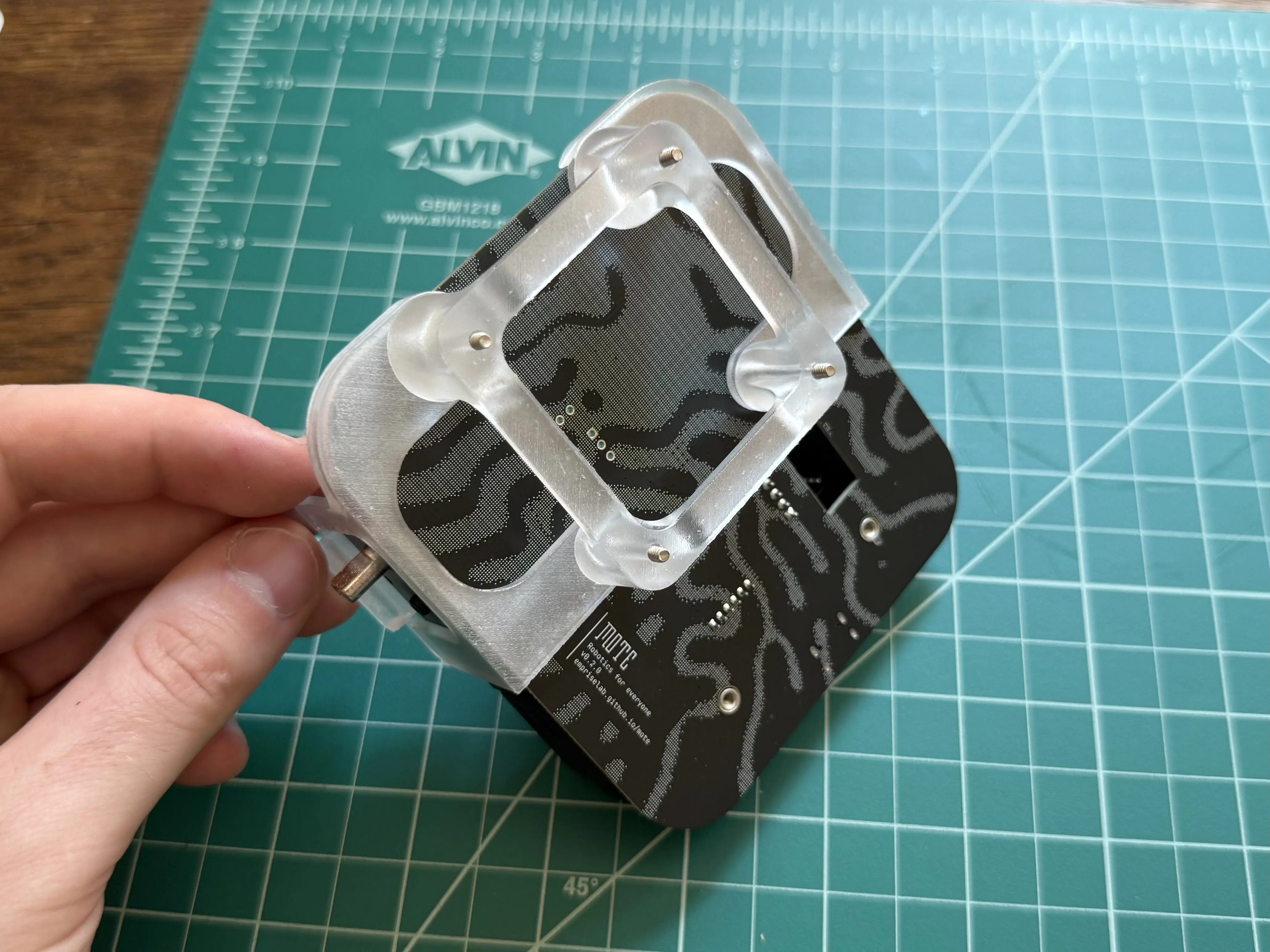
Place the LiDAR stand onto the 25mm screws.
Tip
The legs of the LiDAR stand are not all the same size. Match the radius of the legs with the radius of the motor mounts the legs are placed on.
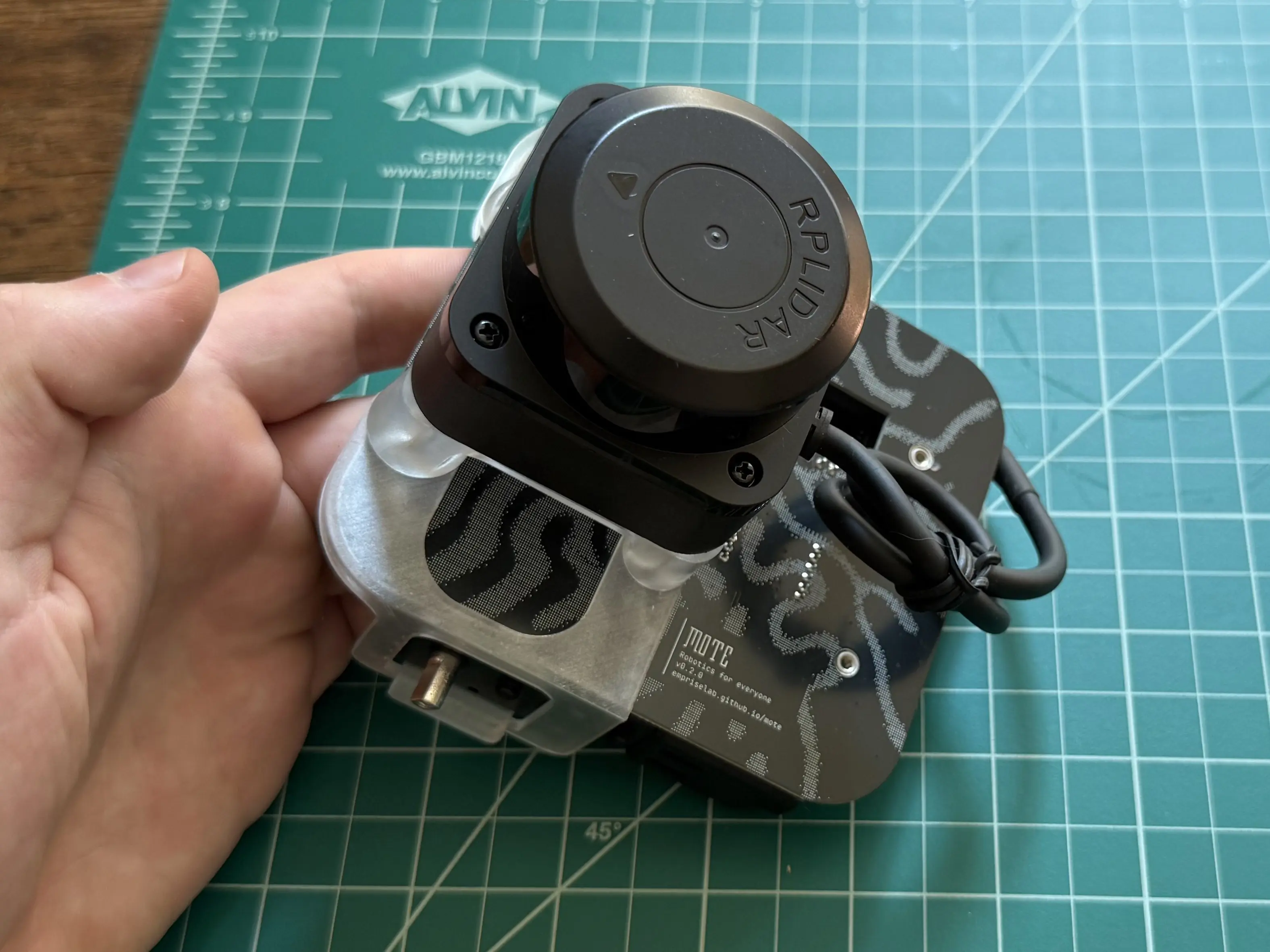
Place the LiDAR on top of the LiDAR stand, then thread the 25mm screws into the LiDAR’s base.
Cables
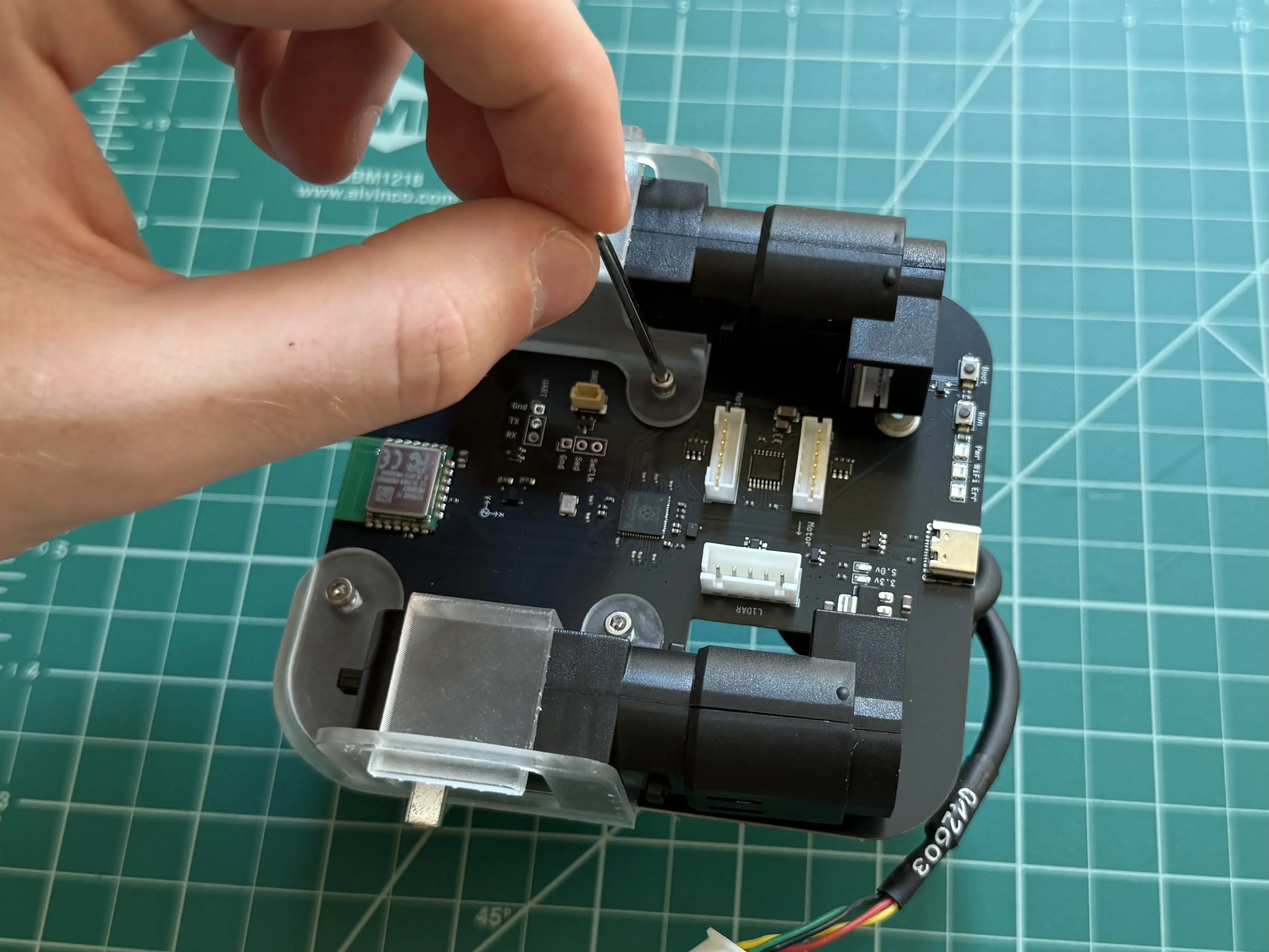
Connect both motors to the circuit board.
Important
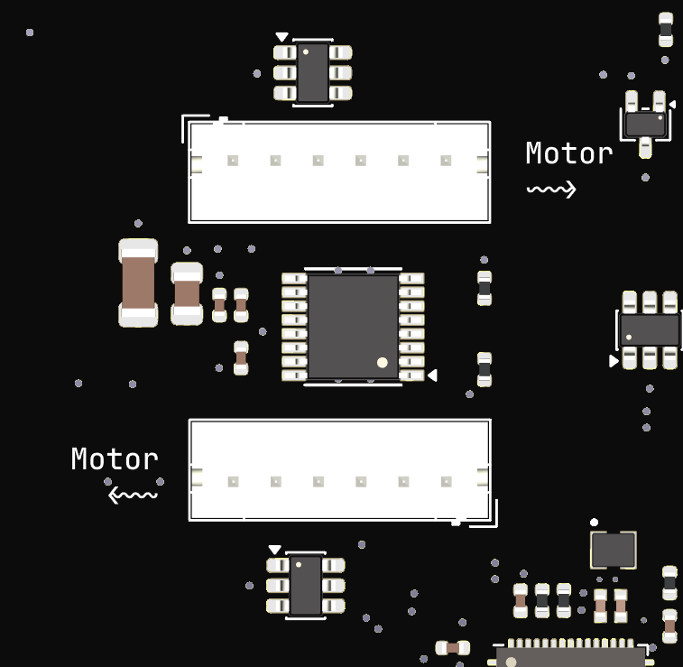
It matters which motor is connected to which socket. Look for the “Motor” arrows on the silkscreen. The arrow points to the motor that should be connected to the respective socket.
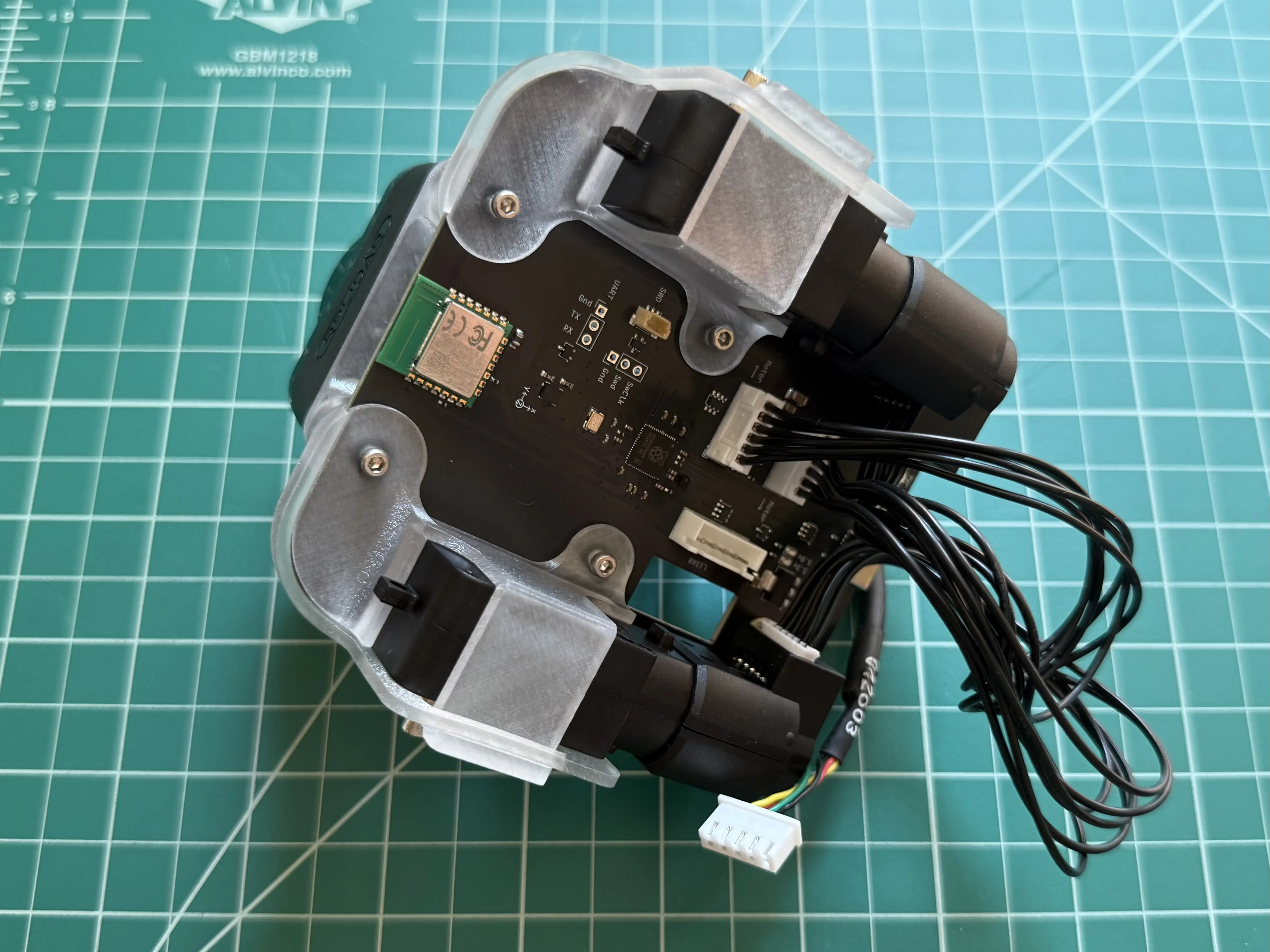
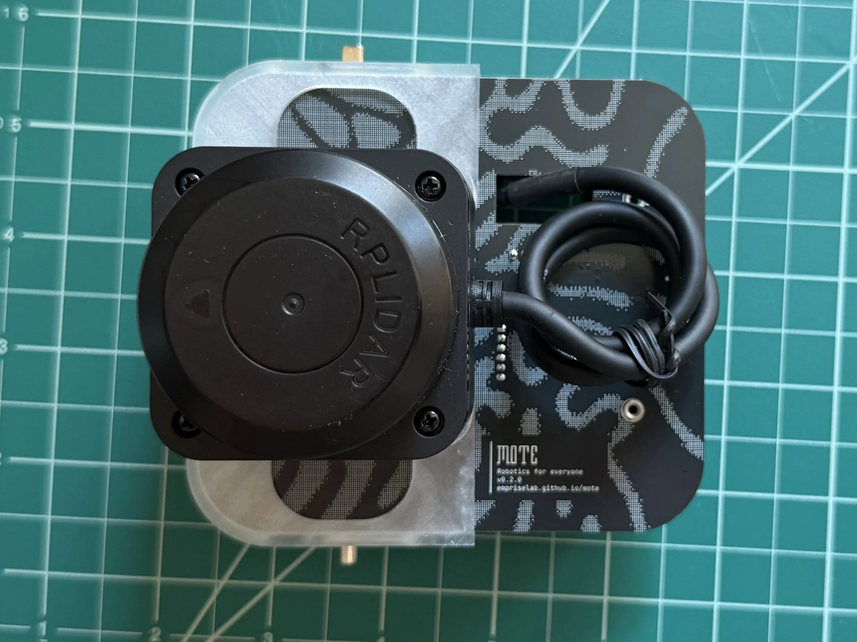
Route the LiDAR’s cable through the hole in the circuit board.
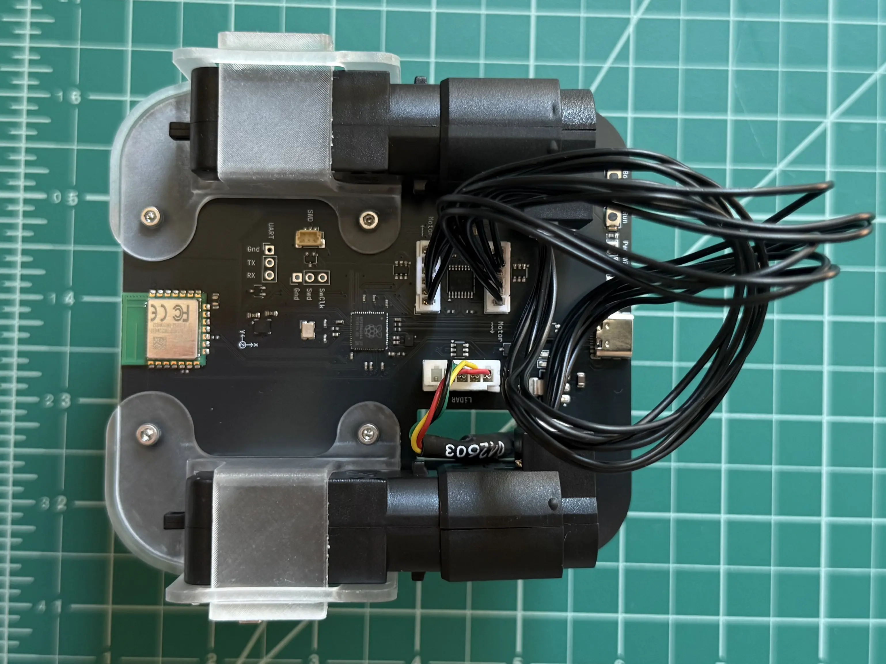
Connect the LiDAR’s cable to the connector on the bottom of the circuit board labeled “LiDAR”.
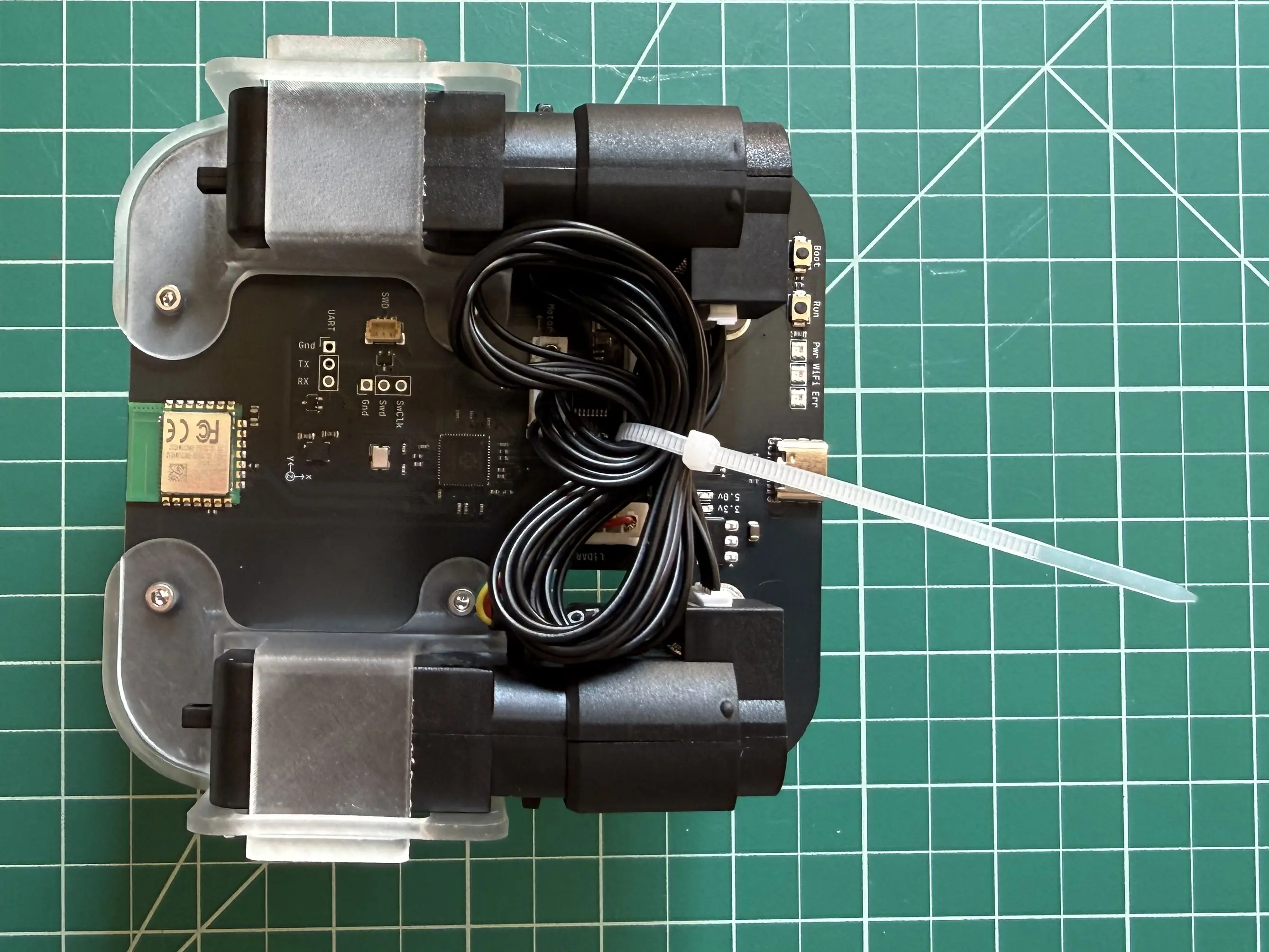
Restrain the motor cables using a cable tie. Trim the cable tie to prevent dragging.
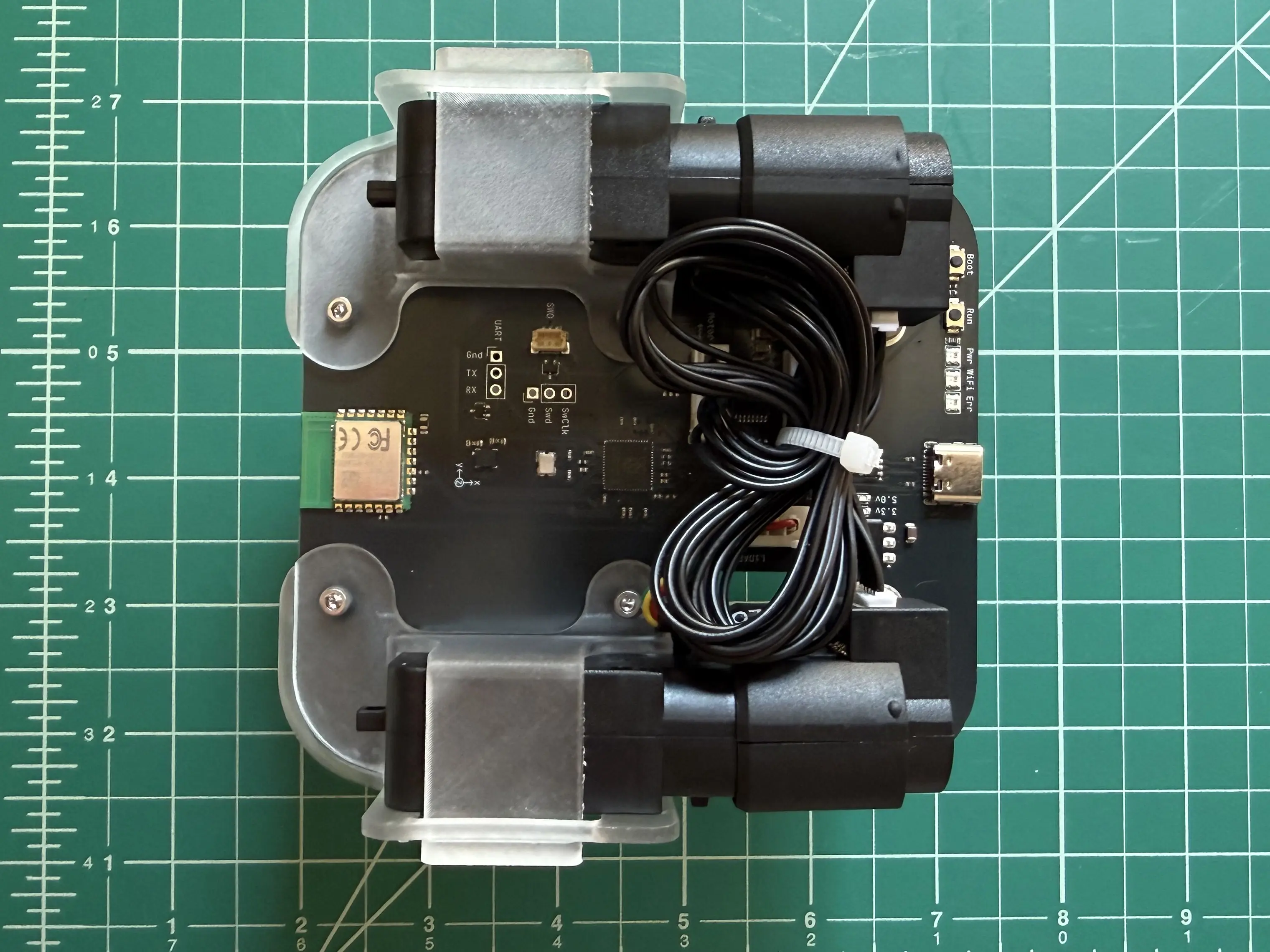
Wheels
Add a wheel spacer to the left motor.
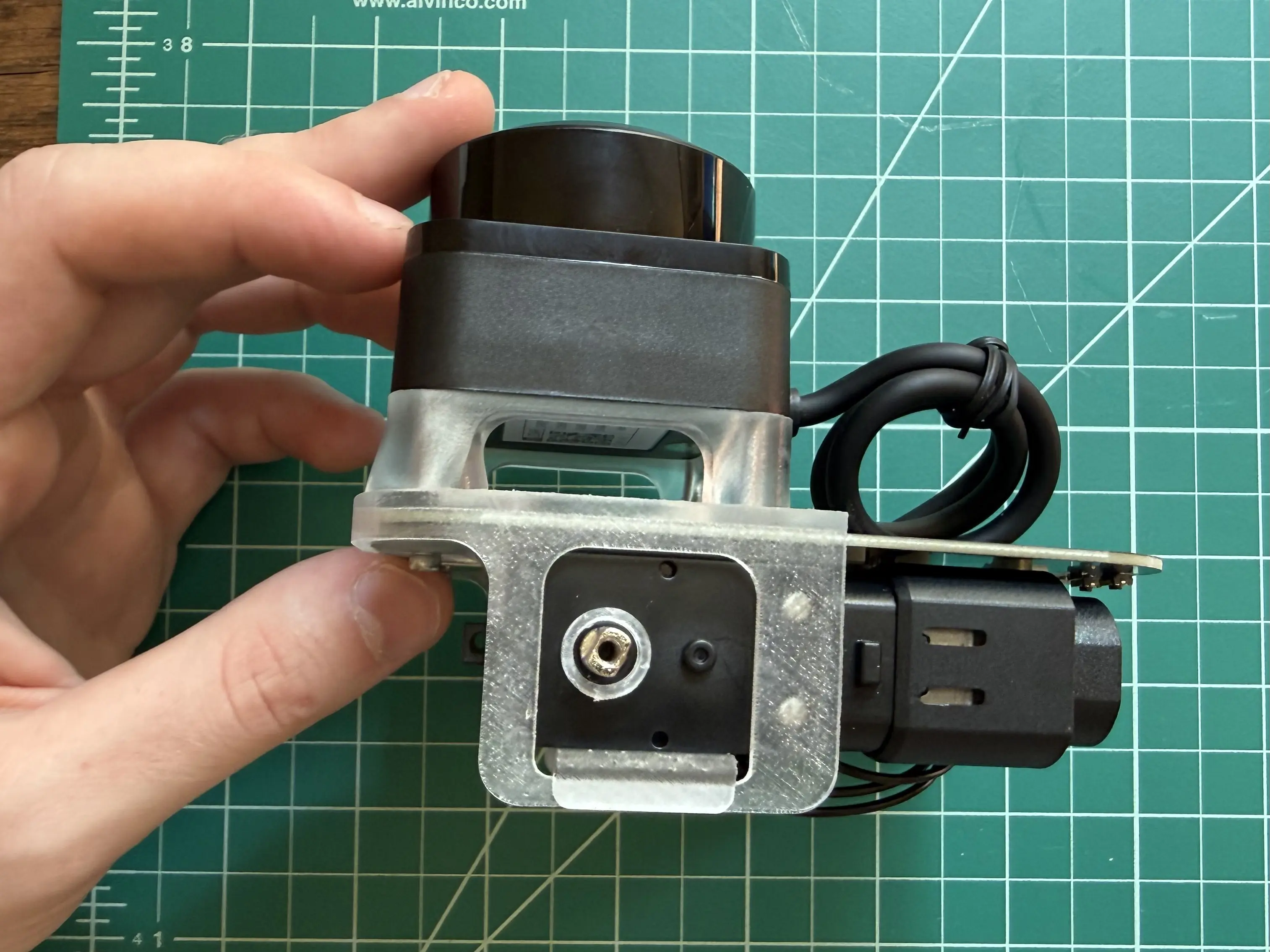
Push the wheel onto the motor shaft.
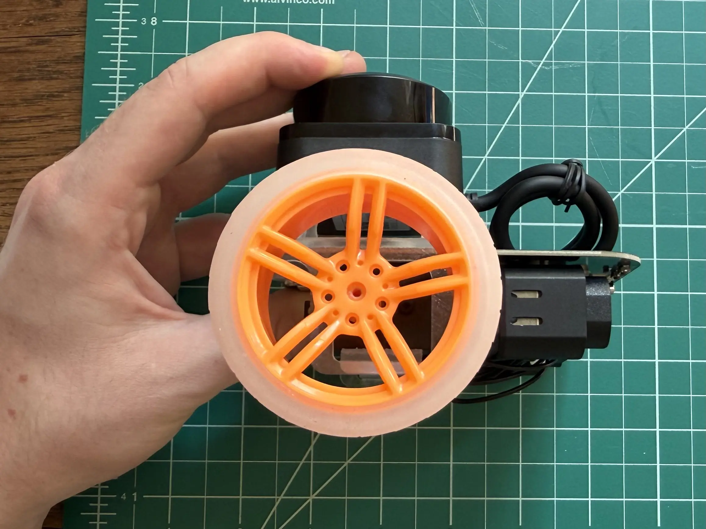
Secure the wheel with a 25mm screw.
Tip
The M2.5 screw must be threaded into the hole on the wheel. You may need to apply some pressure to get the thread started.
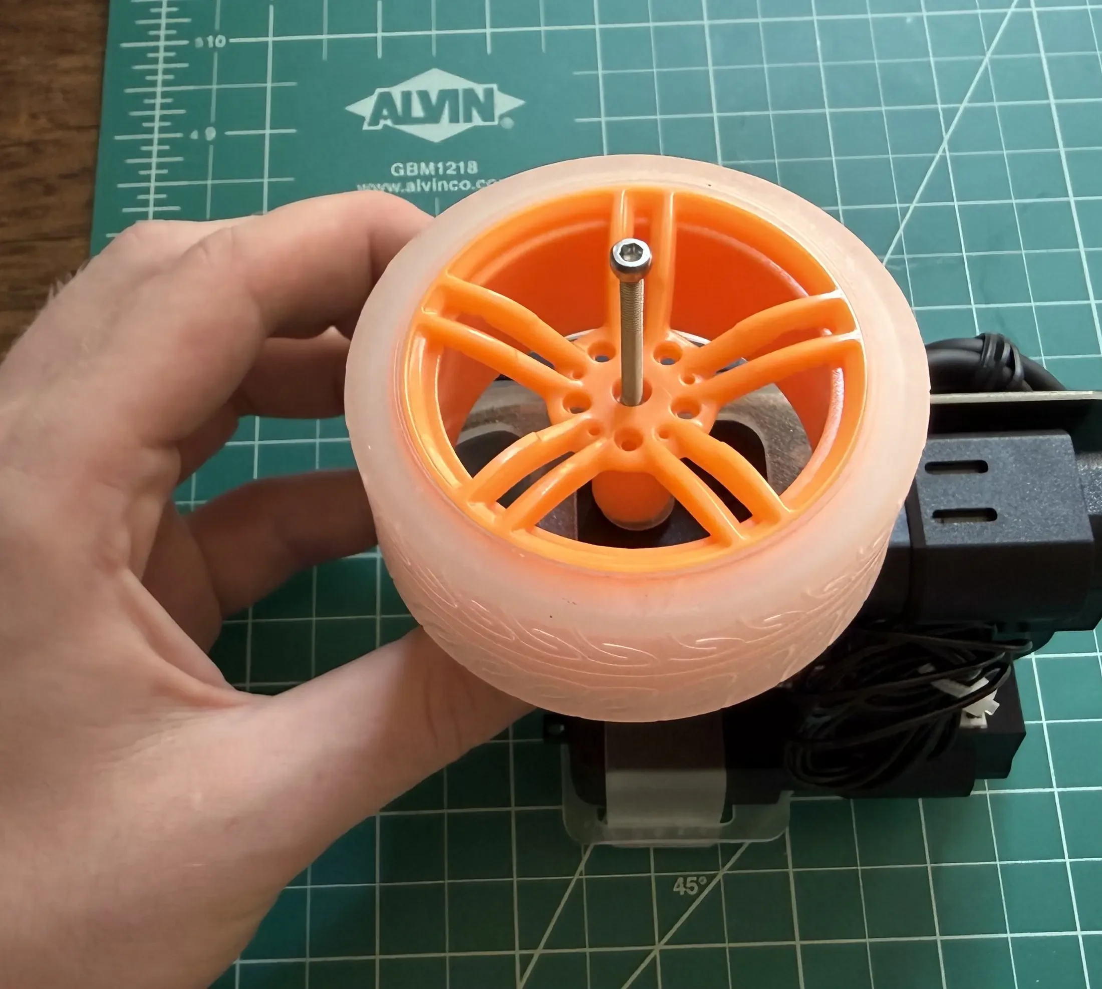
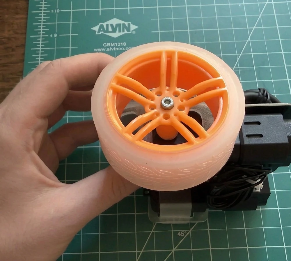
Repeat for the right wheel.
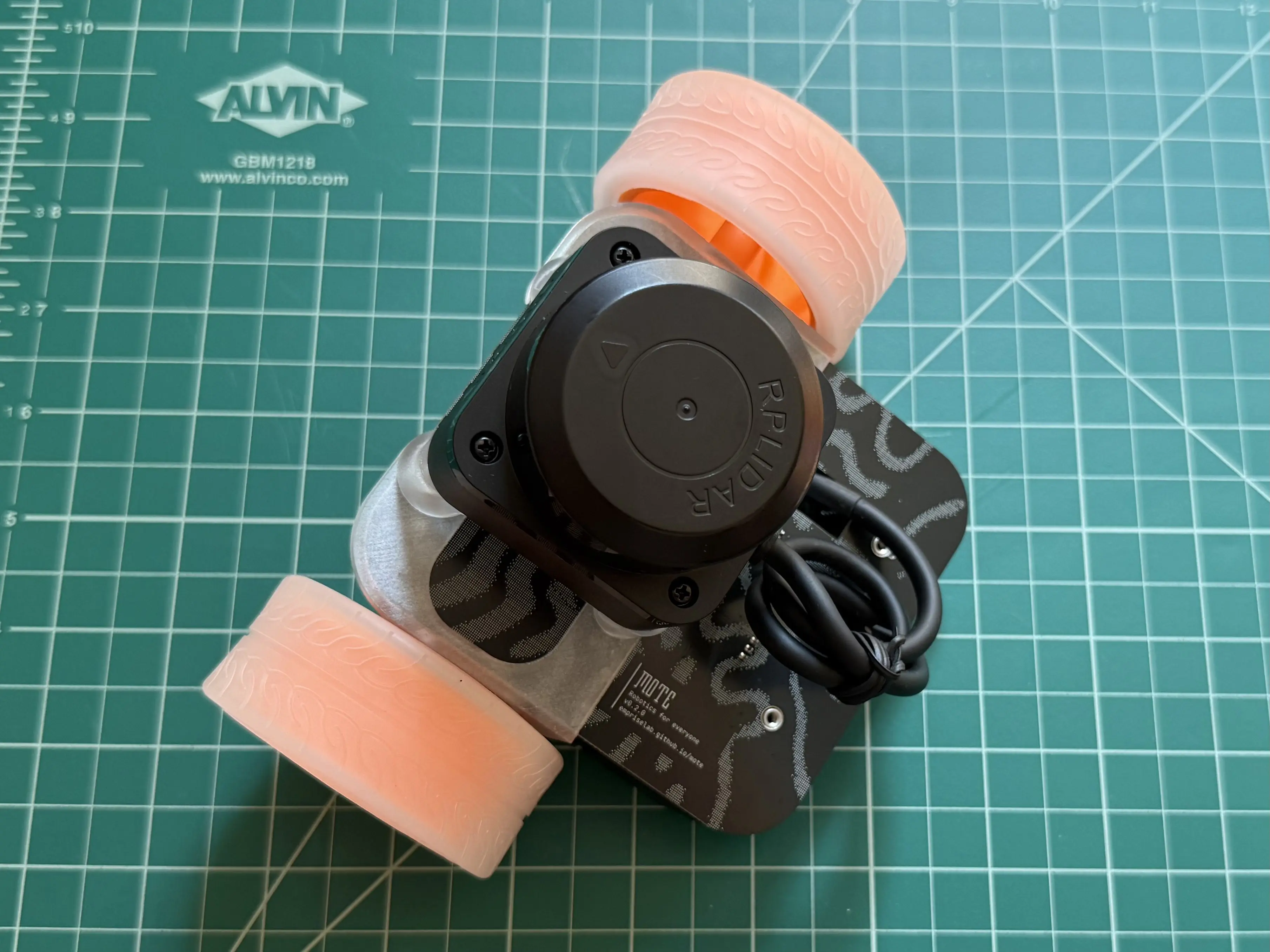
Tail Runner
Place a 6mm screw into the hole on the tail runner. Align the screw with the nut on the circuit board, then use the hex key to secure the tail runner to the circuit board. Repeat with the second 6mm screw and hole on the tail runner.
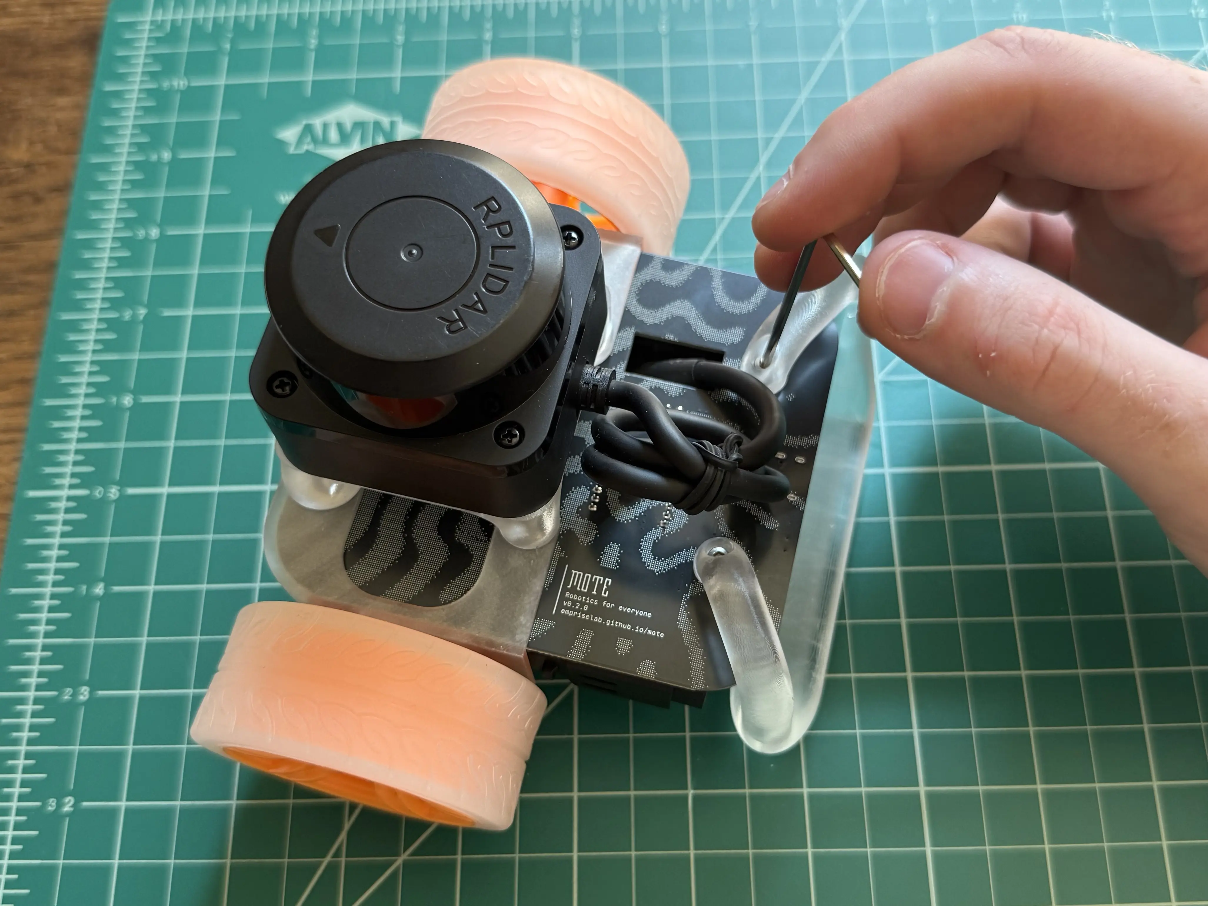
Success
You’ve successfully assembled your Mote!
Next Steps
- Update Firmware - Update your Mote to the latest firmware version
Updating Firmware
Before you can start using your Mote you’ll need to program it with the latest firmware.
-
Download the latest version of mote-firmware: MOTE_FW_TAG_PLACEHOLDER.
-
While holding down the “BOOT” button on your Mote, connect the robot to your computer using the USB-C cable. Mote will appear as a USB drive titled “RP2350”.
-
Drag and drop the mote-firmware UF2 file into the USB drive. The drive will disappear a couple of seconds after dropping in the file.
Next Steps
- Configuration - configure Mote for use on your network
Configuration
This page will guide you through setting up your Mote for the first time.
Connecting to WiFi
Mote communicates using WiFi. In order to work with Mote, we will log it onto a WiFi network.
-
Connect Mote to your computer using a USB-C cable.
-


Open the Mote configuration page. Click
[ connect ]and select “Mote Serial”. -
Locate your WiFi network under “Networks”. Click
[ connect ]and enter your WiFi password. If you are using a public network, leave this field blank. -
Press enter.
-
Wait 30 seconds for Mote to connect to the network. When the robot has successfully connected, you will see “currently connected” next to your WiFi in the detected networks list.
-
Under “Identification”, take note your Mote’s IP. You will need the IP later to establish communication with your robot.
Give Your Mote a Name
You can use a friendly name to communicate with your Mote.
-
Connect Mote to your computer using a USB-C cable.
-
Open the Mote configuration page. Click
[ connect ]and select “Mote Serial”. -
Next to “Unique Identifier”, click
[ update ]. -
Enter your Mote’s name in the box.
-
Press enter.
Important
Only one Mote can have a given name on a single network. If you expect other Motes to be used on the same network, choose a name that is unique enough to prevent conflicts.
Next Steps
- Hello World - learn how to connect to your robot.
Troubleshooting
My network doesn’t appear
Mote can only connect to 2.4 GHz networks. Make sure your router has the 2.4 GHz band enabled.
Hello World
In this example we’ll use the mote-link Python library to control Mote and visualize telemetry data.
Example data - Mote driving around my apartment
Setup
This example uses uv to run a Python program. Install uv using the instructions in the uv docs.
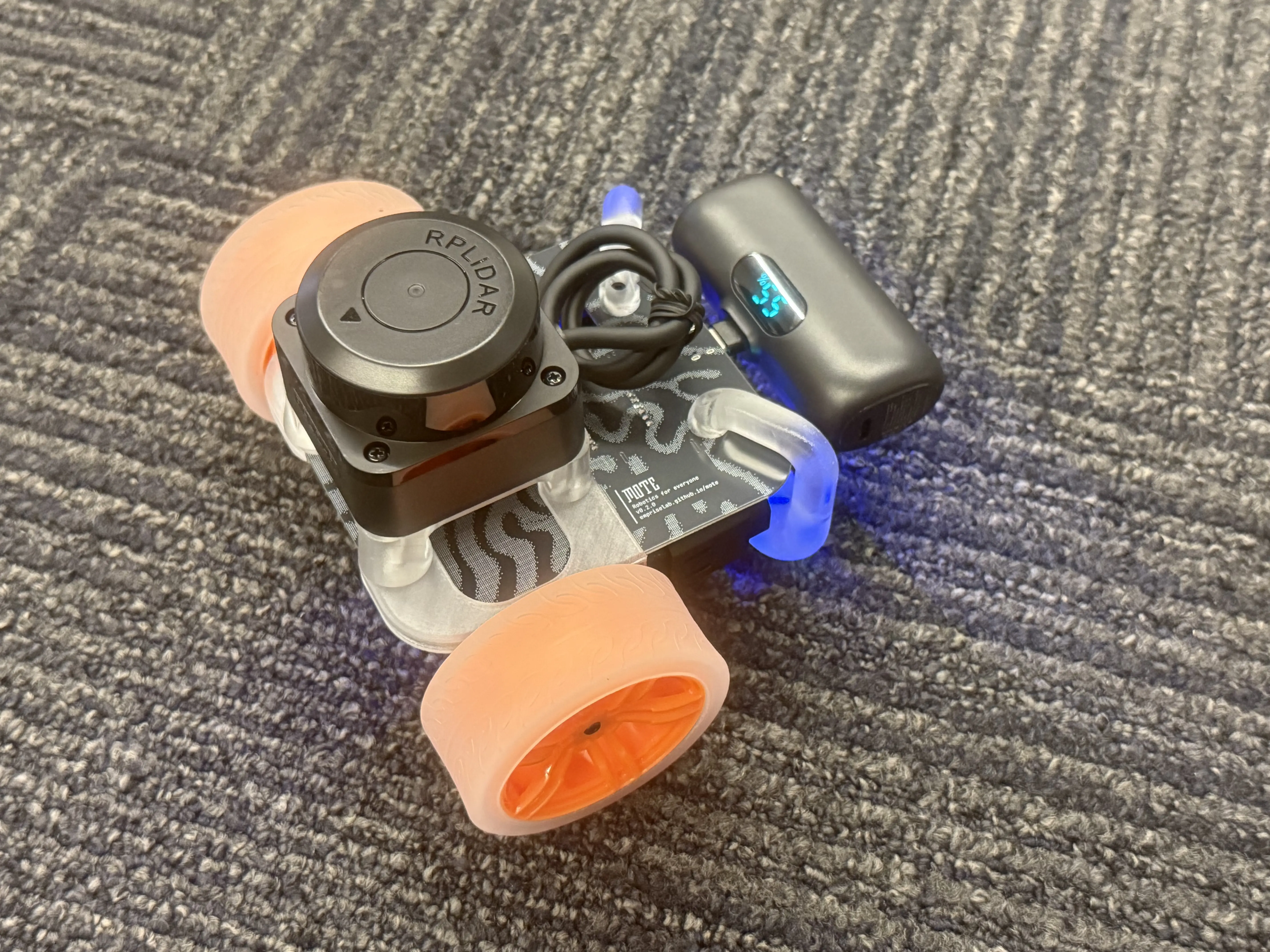
Attach the battery to your Mote. Place your Mote on the ground with enough space for it to move around.
Running the mote-link Demo
In the terminal of your choice, run the demo.
uvx --from 'mote-link[demo]' rerun-demo
Follow the instructions in your terminal to select and connect to your Mote.
Once connected, your browser will open to a dashboard showing realtime LiDAR, wheel encoder, accelerometer, and gyroscope data.
Use the arrow keys to drive Mote around.
Tip
If you know your robot’s name or ip address, you can skip waiting for autodiscovery by passing it in as an argument:
uvx --from 'mote-link[demo]' rerun-demo --ip 192.168.XX.XXor
uvx --from 'mote-link[demo]' rerun-demo --name my-awesome-name
Next Steps
- Python guide - learn how to write your own Python scripts for interfacing with Mote.
- The Rust guide - like the Python guide, but using Rust 🦀.
- The ROS 2 guide - learn how to use Mote with the Robot Operating System.
Troubleshooting
“Could not find Motes using autodiscovery”
Your network has mDNS disabled. This is common practice for public and corporate networks. You can connect directly to your Mote via it’s IP.
-
Connect the robot to your computer using a USB-C cable
-
Note the IP provided under “Identification”.
-
Pass the IP into the demo command
uvx --from 'mote-link[demo]' rerun-demo --ip <IP from the configuration page>
Be aware that Mote’s IP may change between sessions. If that happens, check the configuration page for the new IP.
My Mote drives backwards
Check your motor cable connections. Are the left and right motor connections swapped?
Common Issues
Having issues? Here are some common problems and their solutions.
Don’t see your problem here? Please open an issue on GitHub.
Status LEDs
The underside of Mote has three status LEDs indicating system faults.
PWR LED
The power LED indicates if Mote is receiving sufficient voltage and current to operate. Mote requires a USB C power bank that can deliver at least 1.5A.
🟥 - Not receiving sufficient power
The power supply cannot deliver 1.5A. LiDAR and motors are disabled. Try a different power bank.
🟨 - Cannot read power supply current capacity
This is a firmware or hardware fault. LiDAR and motors are disabled.
🟩 - Nominal
Mote has sufficient power.
WiFi LED
The WiFi LED indicates if WiFi is initialized and connected to a network.
🟥 - WiFi has failed to initialize or is disabled
If the PWR LED is yellow or red, Mote does not have enough power to enable WiFi. If the PWR LED is green, this is a hardware or firmware fault.
🟨 - WiFi has initialized but has not yet connected to a network
Reference getting started - configuration to connect your Mote to a network.
🟩 - Nominal
WiFi is configured and connected to a network.
ERR LED
The error LED indicates if the system’s sensors are powered on and communicating correctly.
🟥 - IMU fault
Power cycle the robot.
🟪 - LiDAR fault
Check that the LiDAR’s cable is securely seated. Power cycle the robot.
🟩 - Nominal
All sensors are operating as expected.
Get Your Mote
Mote uses a custom circuit board that must be manufactured and assembled at a factory. While PCBA has become remarkably affordable in recent years, setup fees make the cost per unit high for small scale runs (1 - 10 units).
If you would like to order a small number of robots, please take a look on the issue tracker and see if a group buy is being coordinated. If you don’t see a group buy posted, reach out to a member of the Mote team and we can help you start one.
If you would like to build many Motes you can start your own manufacturing run. Check out Ordering Circuit Boards for a step by step guide on the process. It’s much easier than it sounds.
All other (non-3D printed) parts are commercially available through standard channels. See the Bill of Materials page for details.
The rest of the robot is 3D printed. The 3D Printed Parts page provides guidance for producing these parts.
Contributing
Mote is an open-source project hosted by Cornell University’s EmPRISE Lab. Thoughtful contributions are welcome and appreciated.
First-time contributors should read through the documentation, then check out the open issues.
Project Structure
mote contains the core libraries required for Mote to function. It includes the following components:
mote-firmware- Embedded firmware for the RP2354 MCU
mote-api- Defines message types and serialization protocols for communicating with Mote
mote-ffi- Foreign Function Interface (FFI)
- Wraps
mote-apiin Python, C++, and Typescript libraries, allowing popular application languages to communicate with Mote
mote-configuration- Webpage used to configure / debug Mote
- Uses the
mote-ffiTypescript library to read / write configuration values, connect the robot to the network, and display errors
mote-hardware- KiCAD circuit board design files
mote-book- You’re reading it!
- Documentation and tutorials
Extension repositories use libraries from mote-ffi to implement bridges to other frameworks.
mote-ros, for example, wraps mote-ffi’s C++ library to implement a Robot Operating System (ROS) node for the robot.
Development Environment
DevContainer
A DevContainer is provided in .devcontainer/.
Open the repo in VS Code with the Dev Containers extension and choose “Reopen in Container”
Tip
probe-rsfirmware deployments will not work on MacOS or Windows due to USB passthrough limitations with Docker Desktop.On native Linux, USB passthrough can be enabled by uncommenting the relevant lines in
.devcontainer/docker-compose.yml.On MacOS and Windows, the firmware binary can be built inside of the dev container with
task firmware:buildand subsequently deployed using a localprobe-rsinstall.
Local Install
Linux and MacOS are officially supported development platforms. Developing on Windows should be possible with some tinkering. If you would like to improve Windows support, please open a pull request.
Install the following tools:
| Tool | Purpose | Installation Method |
|---|---|---|
| rust | cargo (package manager), rustc (compiler), rust-analyzer (language server) | https://rustup.rs/ |
| go-task | task runner | https://taskfile.dev/installation/ |
| uv | python package and project manager | https://docs.astral.sh/uv/getting-started/installation/ |
| node | build / run configuration webpage via typescript, vite, and svelte | https://nodejs.org/en/download |
| probe-rs | flash and debug embedded systems | https://probe.rs/docs/getting-started/installation/ |
| wasm-pack | used for TS - rust interop | cargo install wasm-pack |
| mdBook | documentation generator | https://rust-lang.github.io/mdBook/guide/installation.html |
Building, Testing, Running, and Releasing
Setup
Follow the instructions in Development Environment to set up the required tools.
Make a clone of the repository:
git clone git@github.com:empriselab/mote.git
or
git clone https://github.com/empriselab/mote.git
Build
Compile source and generate executable artifacts.
# Build Mote's firmware
task firmware:build
# Build the configuration webpage
task config:build
# Build the book
task book:build
Test
Run unit tests.
# Run api test cases
task api:test
# Run ffi test cases
task ffi:test
# Test code examples in the book
task book:test
Run
Run a target.
Running firmware requires connecting to Mote using a SWD debug probe.
# Deploy firmware to Mote (first time doing so)
task firmware:provision
# Deploy firmware to Mote (any time after)
task firmware:deploy
# Serve the configuration page
task config:run-dev
# Serve / open the book
task book:open
Release
Release artifacts are built and uploaded automatically via continuous integration.
mote-firmware- Released on any tag to
mote-corematching the patternmote-firmware-vX.X.X, wherevX.X.Xmatches the semantic version of themote-firmwarecrate. - Automated via this GitHub Action.
- Released on any tag to
mote-c- Released on any tag to
mote-corematching the patternmote-c-vX.X.X, wherevX.X.Xmatches the semantic version of themote-fficrate. - The static library, header, and schemas are attached to the release via this GitHub Action.
- Released on any tag to
mote-python- Released on any tag to
mote-corematching the patternmote-python-vX.X.X, wherevX.X.Xmatches the version inmote-ffi/pyproject.toml. - Cross-platform wheels are built and published to PyPI via this GitHub Action.
- Released on any tag to
mote-rust(themote-apicrate)- Released on any tag to
mote-corematching the patternmote-rust-vX.X.X, wherevX.X.Xmatches the semantic version of themote-apicrate. - The crate is published to crates.io via this GitHub Action.
- Released on any tag to
mote-configuration- Released on any tag to
mote-corematching the patternmote-configuration-vX.X.X, wherevX.X.Xmatches the version inmote-configuration/package.json. - The built site is attached to the release via this GitHub Action.
- Released on any tag to
mote-book- Built and deployed to GitHub pages on every commit to main via the GitHub Action.
Contributing to mote-hardware
ECAD
mote-hardware contains the KiCAD v9.0 project files for the Mote circuit board.
Hardware changes are tested on pull request in CI.
Manufacturing files are released on any tag to mote matching the pattern mote-hardware-vX.X.X.
ECAD files are difficult to source control. If you would like to make a contribution to mote-hardware please announce your intention and timeline via the issue tracker.
This helps prevent simultaneous branches that are impossible to merge.
CAD
The PCB outline and 3D printed parts are designed in OnShape. You can copy the OnShape workspace if you would like to make modifications.
To have your changes incorporated into the main design, please create an issue describing your modifications and linking to your copy of the workspace.